Tag: circuit
-
7MHz Transmitter with AVR Soft-keyer
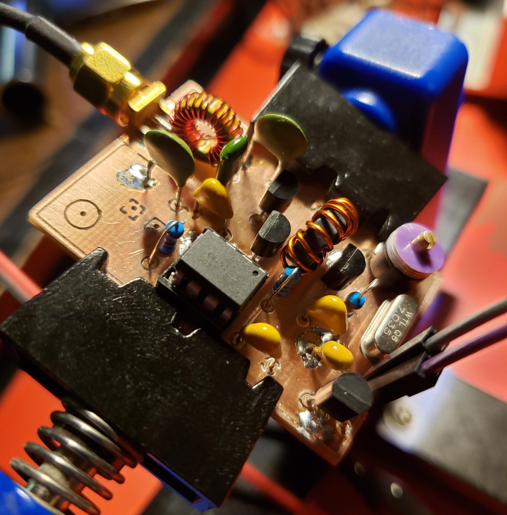
In my last post, I went over the design of a Colpitts crystal oscillator design that put out a moderately clean 7 MHz signal. In order to match the output impedance to 50 Ω, an NPN feedback pair (at least that’s what I’m calling it) was designed. While meeting the specs for driving an ADE-1…
-
7MHz Crystal Oscillator Design
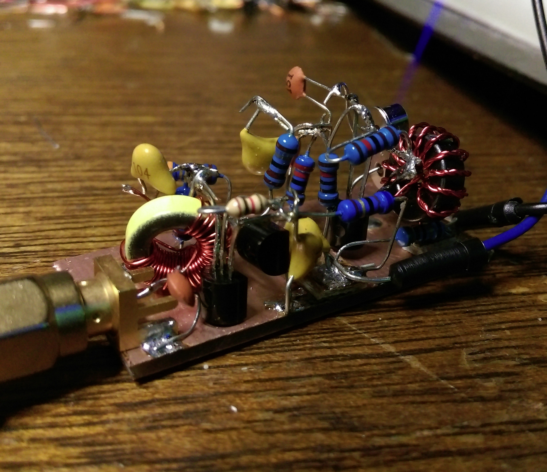
After constructing a 40m wire dipole that works with my SDR setup, I needed to start working on a transmission system. At the heart of virtually any RF system lies a stable oscillator, and crystal oscillators are ubiquitous in many low-power (QRP) rigs simply because they are so stable. After some rough math and a…
-
DOD FX55B SupraDistortion – BigBuff Mod

Here’s another in a line now of DOD pedal mods. For this FX55B, I decided to go for more of a BigMuff sound. Playing around with this pedal initially, I found it to be like most mass-produced distortion/fuzz effects. It had a very thin sound and that notorious volume drop that you may have heard…
-
Class AB amplifier test
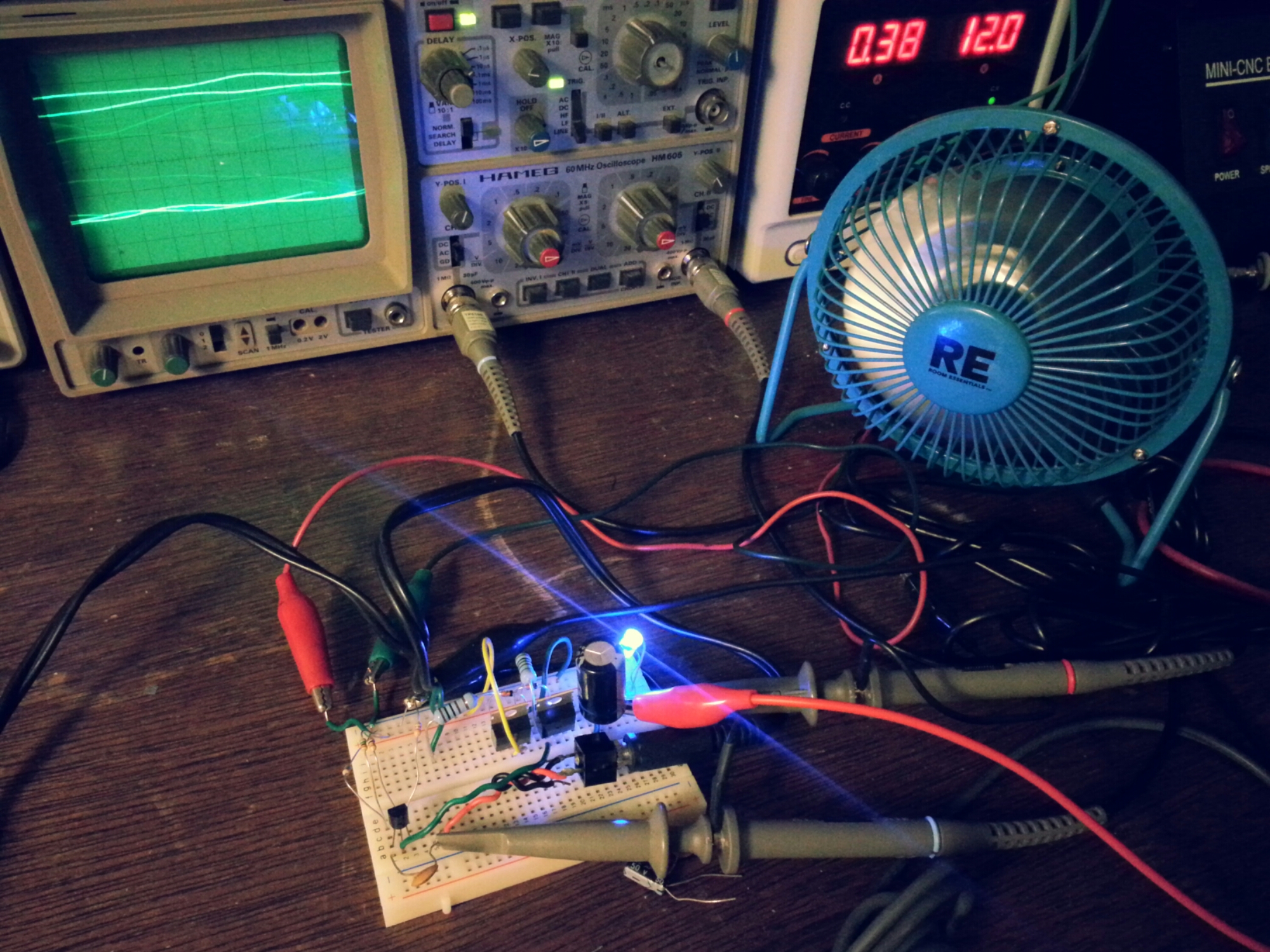
this was an attempt at designing a simple transformer-less class AB amplifier using two BJT power transistors. i setup the USB fan to protect against thermal runaway and cool off the transistors during operation. it took me looking over several schematics to realize that the the emitters of both the PNP and NPN transistors were…
-
LFO modulated simple VCF
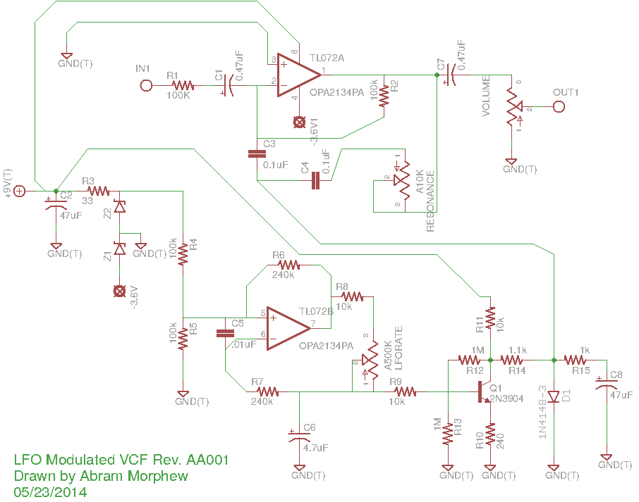
this is a rough draft of a circuit i’ve been working on based of the Simple VCF circuit floating out there. a big thanks to the original author for that. i’m sure there are some mistakes in here. it’s an odd one for sure, but it works on the breadboard. the opamp is a TL072.…
-
initial test of a modulated PT2399 circuit…
a breadboard version of some PT2399 modifications i’ve been working on. there are a lot of DIY schematics that utilize the PT2399 (Magnus Modulus, Echo Base delay, Rebote, etc.). i’ve been interested at trying my hand at modulation techniques recently. i made a simple LFO circuit based on the findings mentioned in a previous post.…
-
experimental PTT signaling switch…
this is an experimental circuit i threw together today. i’ve been working on getting a VOX circuit to work with the Yaesu FT-60R (VX-3R, VX-5, etc.) and Soundmodem on the ol’ Gentoo box. it’s working well, but test packets have been a little iffy.
-
PT2399 build…
this is an older build now, but i wanted to post it while i’ve been on the subject to record the process. believe it or not, i still have some work to do on this one. i used a TL082 as a buffer for the mixing circuit. getting the gain set to my taste has…
-
ngSpice: single frequency FM modulated signal generation
ever wanted to see how that 2N2222 might hold up as a linear RF amplifier? here’s a handy feature of ngSpice that i found recently. i’m rather new to ngSpice and at first was somewhat frustrated by its differences from other SPICE variants. however, i’ve earned a deep appreciation for it and its integration with…