Basic Voltage-Controlled Amplifier

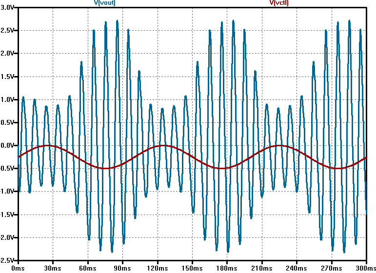
I’ve been looking at the theoretical principles that govern the voltage-controlled amplifier (VCA) recently and came across some simple VCA designs that caught my attention. A common technique involves a JFET and an opamp to achieve VCA type operation by using the JFET as a voltage-controlled resistor somewhere in the input path. I’ve seen a good deal of these circuits out there, but I had trouble getting good simulation results from what I had seen. I cam across an article by Rod Elliot of Elliot Sound Products which covered some nice history and interesting discussion of the VCA in general. After going over the information there, I came up with this design based on some of the more basic designs presented.

Basic VCA LTSpice Schematic

One of the things I’ve been most interested in is trying to accomplish this with a single supply which is common in most stompbox setups. In the schematic, there’s an emitter-follower stage just to act as a buffer for the input signal followed by an inverting opamp stage. To make this work, both C1 and C2 are required to effectively AC couple both input signals (Vin and Vctl) to the opamp stage. There’s an RC network that is supposed to tame the distortion in the output by taking a portion of the output and connecting it to the input of the J201. The article explains this in decent detail. In simulation, the it seems to smooth out the non-linearity of the JFET as Vctl changes. Using the J201, LTSpice gives a decent linear-like response over a range of around 500 mV (0 to -500 mV at the input) and operates decently with a 500 mVp signal.

VCA Linearity Test

For use with an LFO, I found that the best results happen with a slight negative voltage offset and a signal who’s amplitude peaks at 0V (i.e. 250 mV sinusoidal signal with a -250 mV offset). Of course, this is all highly dependent on the threshold voltage of the J201 which can range from -0.3 V to -1.5 V according to the Fairchild datasheet. It will be interesting to see the results of this circuit on a breadboard.

LFO modulated VCA Simulation

References:
[1] Gray, P. (2009). Analysis and design of analog integrated circuits. New York: Wiley.

[2] Sound.whsites.net. (2017). VCAs. [online] Available at: http://sound.whsites.net/articles/vca-techniques.html [Accessed 1 Sep. 2017].

Differential Amplifier w/ Cathode Follower

Differential Amplifier with Cathode Follower

This is a circuit designed for a classroom project whereby the instructions were to “improve” a differential amplifier circuit. The differential amplifier design is essentially an exercise in understanding the inner workings of an opamp, and it effectively works in the same way. The figure below is a schematic for the differential amplifier without the cathode follower output stage. In the LTspice simulation, the input signal is connected to the V+ terminal and the V- terminal is connected to ground. There is no feedback loop between the output and either input terminal making this a high-gain open-loop configuration. However, adding a resistor from V- to ground and one from the output terminal to V- would accomplish the same results as a non-inverting opamp.

diff_amp

I wouldn’t say that adding a cathode follower “improves” the output stage of the amp. It was more an experiment in comparing different solid-state output stages with a vacuum tube stage operating at very low voltages. However, I will say that this thing sounded amazing with the couple of guitars I tested through it. Putting a potentiometer in the feedback network allowed me to play with different gain settings. It’s a very bright sound overall giving lots of high-end sparkle, but the breakup was quite remarkable. I suspect this might be a very usable configuration for a tube mic preamp or a number of audio applications. Hopefully, I will get an opportunity to revisit this before too long.

For those of you interested in the ins and outs of this experiment, you can download our full report here.

LightBox prototype

here’s a small battery-powered guitar amp that i’ve constructed from reused parts. the housing is a busted computer power supply (some of which is in the No. 5) as well. i’ve got several options for this little fellow in mind, but, for now, it’s a tiny amp with a mean distortion. lo-fi enthusiasts should contact me if you’d like one custom built.

LightBox Prototype: a battery-powered guitar amp w/ distortion from abram on Vimeo.

the final layout

final circuit layout with pre-printed PC board

She’s big and bulky, but you can’t ask for too much when you’re dealing with pre-printed PC boards. The 22k resistor in the gain path makes for extremely high output (in terms of headphones). The 100k stereo potentiometer on the output side should make the noise floor a lot lower unless the knob is cranked. That’s what I was going for here since the application of this device will be mainly for when other loud instruments are being played in the room. A short trip to the electronics store should yield three more of these guys. After that, it’s onto the chassis.

the first of four…

IMG_1400

This was my first attempt at building the circuit on the PC board. Unfortunately, I think I’m going to have to get a different board since this one isn’t quite big enough with two opamps. Soldering it is also a bitch considering it’s tiny and my iron tip isn’t as small as it should be.

The 1/8″ plug is the output soon to have a pot attached to it for volume control. I’ve been thinking about attaching an light meter to each channel, but I still need to know what the dimensions of the chassis will be before I jump that far into it.