Arduino: Audio Frequency Generator

Back in good ol’ 2012 (the year the world was supposed to end), I posted some code for a simple Arduino controlled low-frequency oscillator (LFO). It has made its way into some very interesting projects over the years, but recently I was asked in the comments if the code could be modified to have a wider frequency output up into the kHz range. I thought it was a good question, so I made the effort to see what the limitations could be.

How It Works

So, the original LFO employs timers on an ATMega328 (or ATTiny85 depending on which version of the code) to generate the audio output. By using a wave table of a basic sine wave stored in an array, one timer (TIMER0) winds up setting the sample rate by grabbing each sample from the array at a configured interval, and the other timer (TIMER2) creates a PWM output on the selected pin (pin 3 in the code). So by setting an 8-bit value on OCR0A, the sample rate can be adjusted which adjusts the frequency on the output of TIMER2. The datasheet for the ATMega328 gives the following formula for the frequency of the output compare register.

If we take this formula and divide it by the number of samples, we get the output frequency. That means that the output frequency can also be scaled by reducing the number of samples available. So, I made a big output table in LibreOffice and saw that an OCR0A value of 128 was twice the frequency from 255. At 255, I could reduce the number of output samples by half and sweep over the same sample rates but get an increase in output frequency. This introduced a method of frequency scaling. The trade-off, however, is that the sine wave on the output is much less sinusoidal being that it has lower resolution, and that introduces higher order harmonics thus changing the timbre of the sine wave.

Another thing to keep in mind is that the sample rate from the output PWM gets very low and even into the audio range itself. This means that some kind of audio filter is needed on the output. I put a first order low-pass filter using a 2.2k series resistor and a 10 uF capacitor to ground. This worked surprisingly well, though some of the sampling noise shows up on the output at very low frequencies. Being an 8-bit audio signal, this isn’t much to worry about in the grand scheme of things since. I also found that the noise on the output could be lowered by implementing a simple moving average filter in the code on the 10-bit ADC input of the rate control if using a potentiometer to set the frequency. With the timer prescalar set to 64, we should get 64 clock ticks before the next sample is grabbed, so this left some room for some calculations to happen in between sample changes.

It’s all pretty experimental, but it seems to work alright. The frequency range is from around 1 Hz up to 14 kHz (more or less). If you’re using a pot to control the rate, use a linear one as the frequency output gets very logarithmic towards the top of the range.

The Code

// Project: Arduino Audio Frequency Signal Generator
// Version: 1.0
// Author: Abram Morphew
// Date: 2021.10.12

#define cbi(sfr, bit) (_SFR_BYTE(sfr) &= ~_BV(bit))
#define sbi(sfr, bit) (_SFR_BYTE(sfr) |= _BV(bit))

uint8_t sineTable256[] = {
  128,131,134,137,140,143,146,149,152,155,158,162,165,167,170,173,
  176,179,182,185,188,190,193,196,198,201,203,206,208,211,213,215,
  218,220,222,224,226,228,230,232,234,235,237,238,240,241,243,244,
  245,246,248,249,250,250,251,252,253,253,254,254,254,255,255,255,
  255,255,255,255,254,254,254,253,253,252,251,250,250,249,248,246,
  245,244,243,241,240,238,237,235,234,232,230,228,226,224,222,220,
  218,215,213,211,208,206,203,201,198,196,193,190,188,185,182,179,
  176,173,170,167,165,162,158,155,152,149,146,143,140,137,134,131,
  128,124,121,118,115,112,109,106,103,100,97,93,90,88,85,82,
  79,76,73,70,67,65,62,59,57,54,52,49,47,44,42,40,
  37,35,33,31,29,27,25,23,21,20,18,17,15,14,12,11,
  10,9,7,6,5,5,4,3,2,2,1,1,1,0,0,0,
  0,0,0,0,1,1,1,2,2,3,4,5,5,6,7,9,
  10,11,12,14,15,17,18,20,21,23,25,27,29,31,33,35,
  37,40,42,44,47,49,52,54,57,59,62,65,67,70,73,76,
  79,82,85,88,90,93,97,100,103,106,109,112,115,118,121,124
};

uint8_t sineTable128[] = {
  128,134,140,146,152,158,165,170,176,182,188,193,198,203,208,213,
  218,222,226,230,234,237,240,243,245,248,250,251,253,254,254,255,
  255,255,254,254,253,251,250,248,245,243,240,237,234,230,226,222,
  218,213,208,203,198,193,188,182,176,170,165,158,152,146,140,134,
  128,121,115,109,103,97,90,85,79,73,67,62,57,52,47,42,
  37,33,29,25,21,18,15,12,10,7,5,4,2,1,1,0,
  0,0,1,1,2,4,5,7,10,12,15,18,21,25,29,33,
  37,42,47,52,57,62,67,73,79,85,90,97,103,109,115,121 };
  
uint8_t sineTable64[] = {
  128,140,152,165,176,188,198,208,218,226,234,240,245,250,253,254,
  255,254,253,250,245,240,234,226,218,208,198,188,176,165,152,140,
  128,115,103,90,79,67,57,47,37,29,21,15,10,5,2,1,
  0,1,2,5,10,15,21,29,37,47,57,67,79,90,103,115
};

uint8_t sineTable32[] = {
  128,152,176,198,218,234,245,253,255,253,245,234,218,198,176,152,
  128,103,79,57,37,21,10,2,0,2,10,21,37,57,79,103,
};

uint8_t sineTable16[] = {
  128,176,218,245,255,245,218,176,128,79,37,10,0,10,37,79
};

uint8_t sineTable8[] = {
  128,218,255,218,128,37,0,37,128
};

uint8_t sineTable4[] = {
  128,255,128,0,128
};

uint8_t sineTable2[] = {
  255,0
};

uint8_t tWave = 128;
uint8_t sWave = 255;
uint8_t ruWave = 128;
uint8_t rdWave = 128;
uint8_t rWave = 128;
uint8_t inc = 1;
uint8_t r = 0;

int   n = 32;        // number of averages for ADC input (should be a power of 2: 32 max)
int   ocr[32] = {};
int   i = 0;
int   t = 0;    // time delay index for rate sweep
int   sweep = 1023;    // sweep
int   rate = 0;
int   waveform;
byte  d = HIGH;
byte  down = LOW;    // increase freq if LOW, decrease freq if HIGH
byte  rateSelectPin = 1;
byte  waveSelectPin = 0;

void setup() {
  pinMode(waveSelectPin, INPUT);
  pinMode(rateSelectPin, INPUT);
  pinMode(3, OUTPUT);
  setupTimer();
  OCR0A = 128;
}

void loop() {
  // -- Waveform Selection
  waveform = map(analogRead(waveSelectPin),0,1023,1,7);
  //waveform = 1;
  
  // -- Frequency Selection with ADC pin 1
  if (r >= n) r = 0;
  ocr[r] = map(analogRead(rateSelectPin),0,1023,1015,3);
  r++;
  
  // -- ADC input averaging
  for(uint8_t c = 0; c < n; c++) { rate += ocr[c]; }  
  rate = floor(rate / n);
  
  // Uncomment for frequency sweep
  /*--------------------
  if (t >= 2048) {
    sweep--;
    t = 0;
  }
  
  if (sweep <= 4) {
    sweep = 1023;
  }
  t++;
  rate = sweep;
  //----------------------- */

  // rate scaling with increasing frequency
  if (rate < 128) {
    inc = 128;
    rate = rate * 2;
  } else if ((128 <= rate) && (rate < 256)) {
    inc = 64;
    rate = rate;
  } else if ((256 <= rate) && (rate < 384)) {
    inc = 32;
    rate = rate - 128;
  } else if ((384 <= rate) && (rate < 512)) {
    inc = 16;
    rate = rate - 256;
  } else if ((512 <= rate) && (rate < 640)) {
    inc = 8;
    rate = rate - 384;
  } else if ((640 <= rate) && (rate < 768)) {
    inc = 4;
    rate = rate - 512;
  } else if ((768 <= rate) && (rate < 896)) {
    inc = 2;
    rate = rate - 640;
  } else if ((896 <= rate) && (rate < 1024)) {
    inc = 1;
    rate = rate - 768;
  }  
  
  OCR0A = rate;
}

ISR(TIMER0_COMPA_vect) {
  if(i >= (256 / inc)) i = 0;
  switch(waveform) {
    case 1:
      OCR2B = sine(i, inc);      
    break;
    case 2:
      OCR2B = triangle(i);
    break;
    case 3:
      OCR2B = square(i);
    break;
    case 4:
      OCR2B = rampUp(i);
    break;
    case 5:
      OCR2B = rampDown(i);
    break;
    case 6:
      OCR2B = rand(i);
    break;
    case 7:
      OCR2B = white(i);
    break;
  }
  i++;
}

void setupTimer() {
  cli();
/*--- TIMER2 CONFIG ---*/
  sbi(TCCR2A,WGM20);
  sbi(TCCR2A,WGM21);
  cbi(TCCR2A,WGM22);
 
  sbi(TCCR2A,COM2B1);
  cbi(TCCR2A,COM2B0); 
 
  sbi(TCCR2B, CS20);
  cbi(TCCR2B, CS21);
  cbi(TCCR2B, CS22);
   
 /*--- TIMER0 CONFIG ---*/ 
  sbi(TCCR0B,CS00);
  sbi(TCCR0B,CS01);
  cbi(TCCR0B,CS02);

  sbi(TCCR0A, COM0A1);
  cbi(TCCR0A, COM0A0);
    
  cbi(TCCR0A, WGM00);
  sbi(TCCR0A, WGM01);
  cbi(TCCR0A, WGM02);

  cbi(TIFR0,OCF0A);
  sbi(TIMSK0,OCIE0A);
  sei(); 
}

int sine(int i, int inc) {
  if (inc == 1) {
    return sineTable256[i];
  } else if (inc == 2) {
    return sineTable128[i];
  } else if (inc == 4) {
    return sineTable64[i];
  } else if (inc == 8) {
    return sineTable32[i];
  } else if (inc == 16) {
    return sineTable16[i];
   } else if (inc == 32) {
    return sineTable8[i];
  } else if (inc == 64) {
    return sineTable4[i];
  } else if (inc == 128) {
    return sineTable2[i];
  }
}

int triangle(int i) {
  if(tWave >= 255) d = LOW;
  if(tWave <= 0) d = HIGH;
  if(d == HIGH) tWave = tWave + inc;
  if(d == LOW) tWave = tWave + inc;
  return tWave; 
}

int rampUp(int i) {
  ruWave = ruWave + inc;
  if(ruWave > 255) ruWave = 0; 
  return ruWave;
}

int rampDown(int i) {
  rdWave = rdWave + inc;
  if(rdWave < 0) rdWave = 255;
  return rdWave;
}

int square(int i) {
  if(i >= (128 / inc)) sWave = 255;
  if(i < (128/inc)) sWave = 0;
  return sWave;
}

int rand(int i) {
  if(i == (rWave / inc)) rWave = random(255);
  return rWave;
}

int white(int i) {
  return random(255);
}

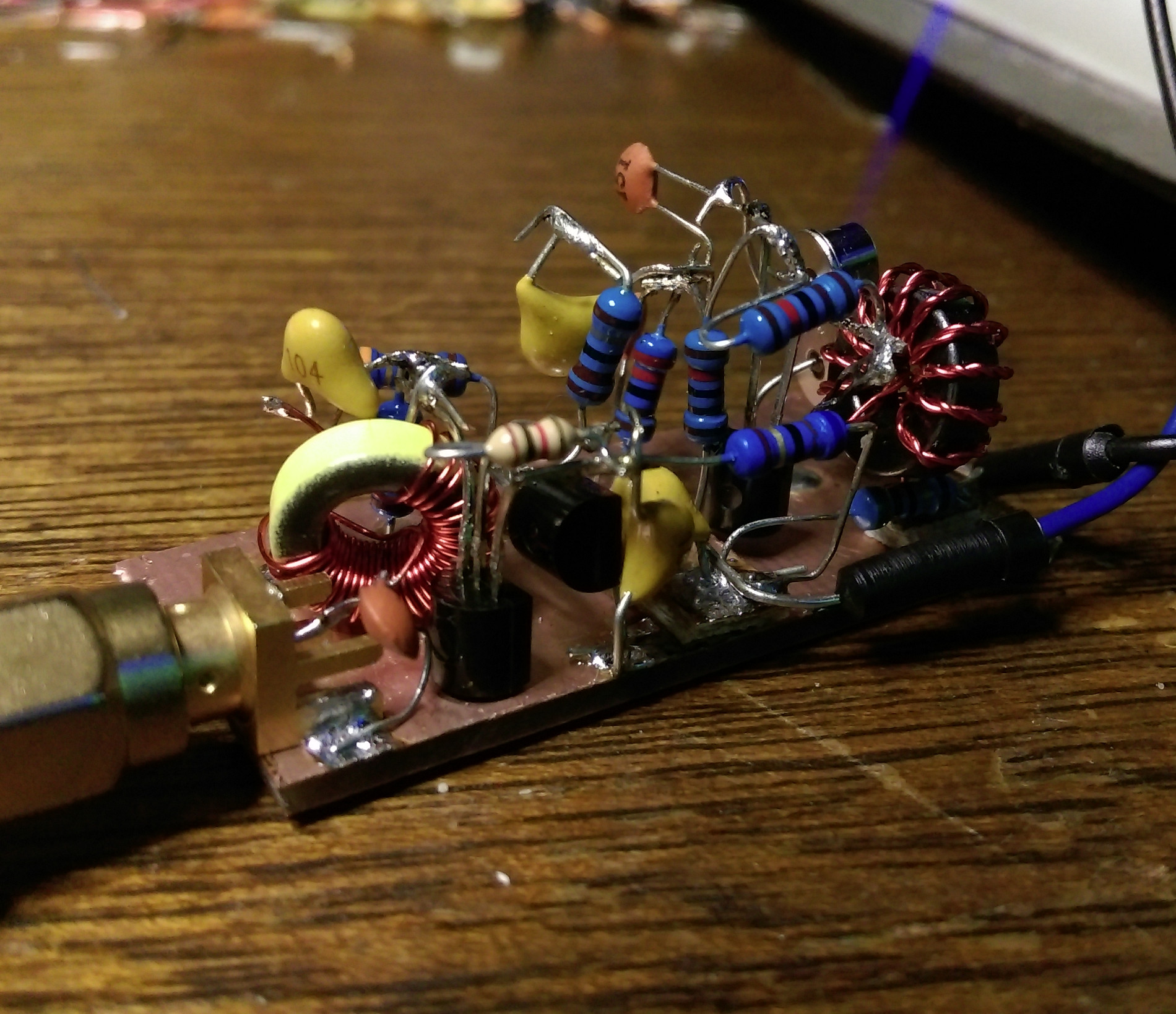
Arduino: 1-Watt 2m Transmitter with RF Signal Generator

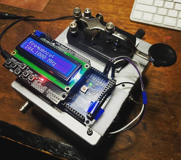
Since I do a lot of RF projects, I wanted to see if I could make a 2m power amplifier using a minimal set of components. I have a number of BS170 MOSFET transistors that I’ve used for dozens of applications over the years from guitar pedal pre-amps to digital control circuits. I started this project by building a class A amplifier on a bare piece of copper laminate. I was able to get 9 dB of gain with a power output of 15 dBm and a quiescent current of 83 mA. The schematic is shown below. R3 and R4 can be omitted if you happen to be building the circuit and replaced with 50 ohm SMA connectors. I used a variable cap at C3 to tune the circuit for maximum output power,

With 15 dBm of output power, I thought this would be adequate to drive a power amplifier stage. I nabbed some 2SC1970 transistors off eBay for a few bucks and started experimenting with the application circuit in the datasheet. This transistor is quite old by modern standards, but they were cheap and in a TO-220 package, so I figured they could take a beating. The standard application circuit was a good jumping off point for starting the design, and I was able to easily make changes to the air-core inductors by compressing and stretching the windings. I wound up just getting as close as I could with the inductors and relying on the variable capacitors in the circuit to get as much power as I could.

The LO portion of the transmitter was an Si5351 clock signal generator controlled by an ATMega2560 Arduino board. It’s able to get up to 160 MHz (200 MHz now in the Si5351B chips) and is programmed via an I2C port. I setup button 5 (Select) on the LCD shield to enable the LO later on, but I just had it running originally at startup and then connected the straight key in series with the 12V supply (widow-maker style) to the PA.

Above is the measured output on the old Tektronix TDS 360 oscilloscope. Measured power output is right at 1 watt. The second harmonic is a little higher than I would have liked, but an added LPF to the output should help fix that right up. The last thing to do was to get out in the rain in January and see if someone could pick it up. I hooked up a 3-element yagi to the output and the signal from the transmitter was picked up by W7YOZ in Shelton, WA some 22 miles to the north east.

Of course, here is the Arduino code for the RF signal generator using the Adafruit Si5351 clock generator board. The controls need to be incorporated into an interrupt trigger to make the thing more controllable, but it hasn’t been so annoying that I’ve needed to fix it as of yet. Just fair warning in case someone out there in the world decides to use it for anything.

// Arduino RF Signal Generator
// author: Abram Morphew
// date: 2019.04.25

#include <Wire.h>
#include <Adafruit_SI5351.h>
#include <LiquidCrystal.h>

Adafruit_SI5351 clockgen = Adafruit_SI5351();
LiquidCrystal lcd(8, 9, 4, 5, 6, 7);

long frequency = 144100000;
long inc = 1000;
char* data = "0";
int btn = 0;
bool keyPress = false;
bool enable = false;

void setup() {
  lcd.begin(16,2);
  lcd.print("Initialize");
  delay(500);
  
  /* Initialise the sensor */
  if (clockgen.begin() != ERROR_NONE) {
    lcd.print("Ooops, no Si5351 detected ... Check your wiring or I2C ADDR!");
    while(1);
  }

  setfrequency(frequency);
  delay(100);
  lcd.clear();
  
}

void loop() {
  if (keyPress == true) {
    setfrequency(frequency);
    keyPress = false;
  }
  
  // set title:
  lcd.setCursor(0,0);
  lcd.print("Frequency: ");

  // update frequency 
  lcd.setCursor(0, 1);
  lcd.print(frequency/1e6,3);
  lcd.print(" MHz ");

  btn = readkeypad();
  if ((btn == 1) &amp;&amp; (frequency + inc &lt;= 155e6)) { frequency = frequency + inc; keyPress = true; delay(100); }
  if ((btn == 2) &amp;&amp; (frequency - inc &gt;= 420e3)) { frequency = frequency - inc; keyPress = true; delay(100); }

  if ((btn == 3) &amp;&amp; (inc &lt; 1e8)) { inc = inc * 10; delay(100); }
  if ((btn == 4) &amp;&amp; (inc &gt; 1e4)) { inc = inc / 10; delay(100); } 
  if (btn == 5) {
    clockgen.enableOutputs(true);
  }  
  
  if (btn != 5) {
    clockgen.enableOutputs(false);
  }
  
  delay(10);
}

int readkeypad(){
      int adc_key_in = analogRead(0); //
      int ret = 0;

      if (adc_key_in &lt; 50) ret = 4;
      if ( (adc_key_in &gt; 800) &amp;&amp; (adc_key_in &lt; 1150)) ret = 0;
      if ( (adc_key_in &gt;  80) &amp;&amp; (adc_key_in &lt; 150) ) ret = 1;
      if ( (adc_key_in &gt; 250) &amp;&amp; (adc_key_in &lt; 350) ) ret = 2;
      if ( (adc_key_in &gt; 400) &amp;&amp; (adc_key_in &lt; 500) ) ret = 3;
      if ( (adc_key_in &gt; 500) &amp;&amp; (adc_key_in &lt; 800) ) ret = 5;
  
      
      //lcd.print(adc_key_in);
      return ret;
 }

int setfrequency(long frequency) {
  int m = 0;
  int n = 0;
  int fs = 8;
  clockgen.enableOutputs(false);

  if (frequency &gt; 55e6) {
    fs = 8;
  } else if ((frequency &lt;= 55e6) &amp;&amp; (frequency &gt; 25e6)) {
    fs = 16;
  } else if ((frequency &lt;= 25e6) &amp;&amp; (frequency &gt; 10e6)) {
    fs = 32;
  } else if ((frequency &lt;= 10e6) &amp;&amp; (frequency &gt; 6e6)) {
    fs = 64;
  } else if ((frequency &lt;= 6e6) &amp;&amp; (frequency &gt; 3e6)) {
    fs = 128;
  } else if ((frequency &lt;= 6e6) &amp;&amp; (frequency &gt; 2.1e6)) {
    fs = 256;
  } else if ((frequency &lt;= 2.1e6) &amp;&amp; (frequency &gt; 1e6)) {
    fs = 512;
  } else if (frequency &lt;= 1e6) {
    fs = 900;
  }

  // determine m, n, and d from frequency value
  m = floor(frequency*fs/25e6);
  n = ((frequency*fs/25e6) - m)*1000;
  clockgen.setupPLL(SI5351_PLL_A, m, n, 1000);
  clockgen.setupMultisynth(0, SI5351_PLL_A, fs, 0, 1);
}

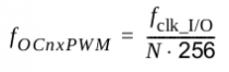
200 kHz Arduino Clock Generator

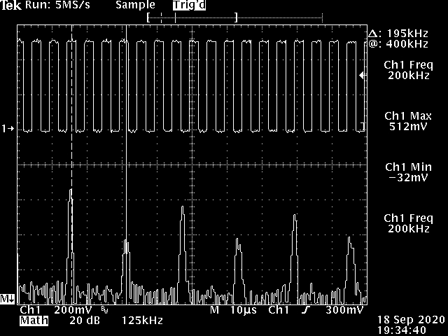
Someone contacted me recently about using an ATMega328 to generate a 200 kHz clock signal for a BBD analog delay chip. I finally had a few minutes today to sit down and ensure that this code works. Varying the OCR0A value acts as a frequency adjustment on the output following the formula: f = 16e6 / (4 * OCR0A) where OCR0A != 0. With a value of 0, the output frequency is roughly 8 MHz. It seemed fairly stable enough at this frequency, but I imagine that it would start having issues with more instructions. Either way, it makes for a very usable clock signal in the kHz range. I’ll try it out on a BBD hopefully one day myself and see.

// ===== 200 kHz Clock Signal Generator ==== //
int  pin = 6;
byte data = LOW;

void setup() {
  setupTimer();
  pinMode(pin, OUTPUT);
                 // f = 16e6 / (4 * OCR0A)
  OCR0A = 20;    // varies CLK frequency: 0 =&gt; 8 MHz, 255 =&gt; 16 kHz
  digitalWrite(pin,data);
}

void loop() {

}

void setupTimer() {
  cli(); 
 /*--- TIMER0 CONFIG ---*/  
  TCCR0A = 0b11000001;
  TCCR0B = 0b00001001;    // last 3 bits set prescalar for Timer0
  TIMSK0 = 0b00000010;    // set OCIE0A high
  TIFR0  = 0b00000010;    // set OCF0A high
  sei(); 
}

ISR(TIMER0_COMPA_vect) {
  data = !data;
  digitalWrite(pin, data);
}
</pre>

7MHz Transmitter with AVR Soft-keyer

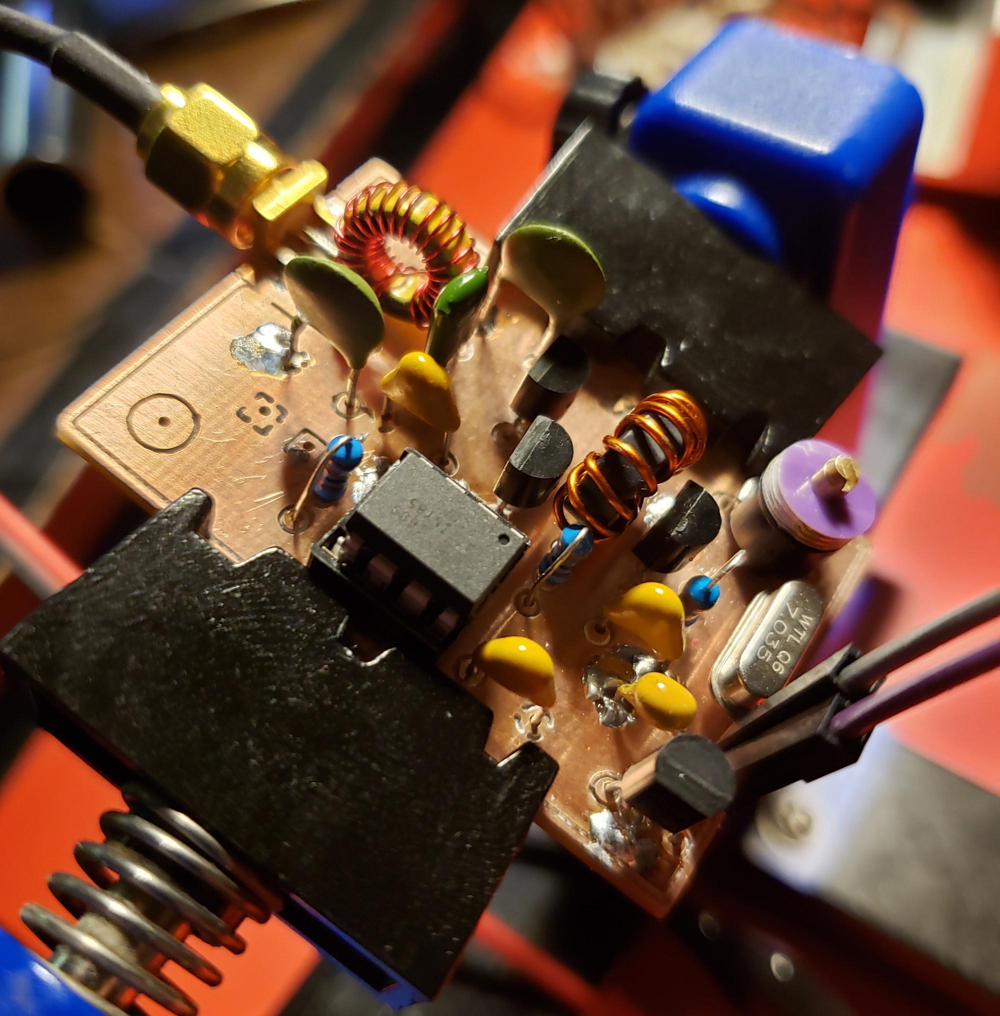
In my last post, I went over the design of a Colpitts crystal oscillator design that put out a moderately clean 7 MHz signal. In order to match the output impedance to 50 Ω, an NPN feedback pair (at least that’s what I’m calling it) was designed. While meeting the specs for driving an ADE-1 mixer, it consumed an unnecessary amount of current. I’ve been designing a tremolo effect recently (which I should be making on post on as well in the future) where I used a BS170 MOSFET to amplitude modulate an incoming audio signal. Without going into too much detail, I decided to adjust the DC bias point of an emitter-follower to sit at the threshold voltage of the BS170 to prevent from having to have a DC block immediately followed by another DC bias point. While looking at different transmitter designs on Homebrew RF Circuit Design Ideas, I came across a class C amplifier that used a similar technique to what I was doing in the tremolo effect combined with a Pierce oscillator. I did some experimentation and came up with the following circuit.

To be fair, this schematic is revision B, and it hasn’t been built yet. Revision A, however, is pretty much the same thing except R1 is omitted and the drain of Q3 connects to the source of Q6. The ATTiny85 takes the single-throw switch as the only input. When you turn it on, the switch acts like a standard on-off keyer for banging out morse code. If you hold the key down for 5 seconds, it changes to a beacon mode and starts tapping out my call sign. Holding the key down again changes operation into pulse mode with a frequency around 1 kHz. In pulse mode, you can actually pick up the signal on a standard AM receiver as seen in the demo video. The transmitter itself puts out 28 dBm running on a 12V supply and is around 82% efficient.

The PCB layout came out pretty quickly. It was the first time I have ever done double-sided PCB etching. Overall, I think it came out pretty well. There was small offset as you can see from the placement of the drill holes, but no harm, no foul. Performance was even a little better than the prototype. I mounted the board inside a Hammond 1590A enclosure and made a short demonstration video. It’s extremely simple, but I think it will be a useful piece of a larger project that I’m working on. It can also be easily adapted to a number of frequencies using a different crystal or loading Q2 to act as a frequency multiplier. I did experiment with this somewhat and was able to produce fairly strong second and third harmonics at the output. That’s about as far as I got though since I got distracted making theremin type sounds on my shortwave radio receiver.

#define cbi(sfr, bit) (_SFR_BYTE(sfr) &amp;= ~_BV(bit))
#define sbi(sfr, bit) (_SFR_BYTE(sfr) |= _BV(bit))

#define CTL 0         // TX enable pin
#define SW  3        // input switch pin
#define N   10      // N periods in monopulse mode

bool            sw = LOW; 
bool            trig = LOW;               // monopulse trigger status
bool            tx = LOW;                // flag for TX enable
bool            keyer = LOW;            // flag for start of key press
int             mode = 0;              // modes: 0 =&gt; Key mode (default), 1 =&gt; ID mode, 2 =&gt; Monopulse
int             dit = 50;             // delay time for dit in ms
int             dash = 150;          // delay time for dash in ms
unsigned long   hold = 5e6;         // max hold value in microseconds
unsigned long   pause = 1e7;       // max pause between IDs in microseconds 
unsigned long   start = 0;        // start time in microseconds
unsigned long   last = 0;        // time of last ID;
long            c = 0;          // count variable for mode change


void setup() {
  pinMode(CTL,OUTPUT);
  pinMode(SW, INPUT);

  cli(); 
  /*--- TIMER1 CONFIG ---*/  
  TCCR1  = 0b01101000;
  GTCCR  = 0b00100000;
  
  TCCR0A = 0b00100000;
  TCCR0B = 0b00001011;    // last 3 bits set prescalar for Timer0

  cbi(TIFR,OCF1A);
  sbi(TIMSK,OCIE1A);
  OCR1A = 128;
  sei();

/* --- interrupt enable
    GIMSK = 0b00100000;     // turns on pin change interrupts
    PCMSK = 0b00001000;    // turn on interrupts on pins PB3
    sei(); 
*/
}

void loop() {  
  /*
    if (sw == LOW) { 
      start = micros();
      if (keyer == HIGH) {
       modeChk(); 
      } else {
       keyer = HIGH;
      }
    } else {
     keyer = LOW;
    }
  */
  // perform function based on mode
  switch(mode) {
    case 0:
      if (sw == LOW) {
        digitalWrite(CTL, HIGH); 
      } else {
        digitalWrite(CTL, LOW);
      }
    break;
    
    case 1:
      if (last == 0) {
        id();
      } else if ((micros() - last) &gt; pause) {
        id();
      }
    break;
    
    case 2:
      if (sw == LOW) {
        pulse();
      }
    break;
  }

  trig = LOW;                 // monopulse trigger reset  
}

ISR(TIMER1_COMPA_vect) {
    sw = digitalRead(SW);
    if (sw == LOW) { 
      if (keyer == HIGH) {
       modeChk(); 
      } else {
       start = micros();
       keyer = HIGH;
       trig = HIGH;
      }
    } else {
     keyer = LOW;
    }
} 

void modeChk() {
  if ((micros() - start) &gt; hold) {
     if (mode &lt; 2) {
       mode++;
     } else {
       mode = 0;
     }
     start = micros();
     stat();
     delay(1000);
  }
}

void pulse() {
  // pulse TX on and off N times
  for(int n = 0; n &lt; N; n++) {
      digitalWrite(CTL,HIGH);
      delayMicroseconds(500);
      digitalWrite(CTL,LOW);
      delayMicroseconds(500);
  }
}

void stat() {
  // tap out mode number in morse code
  for(int n = 0; n &lt; mode; n++) {
      digitalWrite(CTL,HIGH);
      delay(dit);
      digitalWrite(CTL,LOW);
      delay(dit);
  }

    for(int n = 0; n &lt; (5 - mode); n++) {
      digitalWrite(CTL,HIGH);
      delay(dash);
      digitalWrite(CTL,LOW);
      delay(dit);
  }
}

void id() {
  // tap out ID for K2NXF
  
// K
  digitalWrite(CTL,HIGH);
  delay(dash);
  digitalWrite(CTL,LOW);
  delay(dit);
  digitalWrite(CTL,HIGH);
  delay(dit);
  digitalWrite(CTL,LOW);
  delay(dit);
  digitalWrite(CTL,HIGH);
  delay(dash);

  digitalWrite(CTL,LOW);
  delay(dash);
  
// 2 
  digitalWrite(CTL,HIGH);
  delay(dit);
  digitalWrite(CTL,LOW);
  delay(dit);
  digitalWrite(CTL,HIGH);
  delay(dit);
  digitalWrite(CTL,LOW);
  delay(dit);
  digitalWrite(CTL,HIGH);
  delay(dash);
  digitalWrite(CTL,LOW);
  delay(dit);
  digitalWrite(CTL,HIGH);
  delay(dash);
  digitalWrite(CTL,LOW);
  delay(dit);
  digitalWrite(CTL,HIGH);
  delay(dash);
  digitalWrite(CTL,LOW);
  delay(dash);

// N
  digitalWrite(CTL,HIGH);
  delay(dash);
  digitalWrite(CTL,LOW);
  delay(dit);
  digitalWrite(CTL,HIGH);
  delay(dit);
  digitalWrite(CTL,LOW);
  delay(dash);

// X
  digitalWrite(CTL,HIGH);
  delay(dash);
  digitalWrite(CTL,LOW);
  delay(dit);
  digitalWrite(CTL,HIGH);
  delay(dit);
  digitalWrite(CTL,LOW);
  delay(dit);
  digitalWrite(CTL,HIGH);
  delay(dit);
  digitalWrite(CTL,LOW);
  delay(dit);
  digitalWrite(CTL,HIGH);
  delay(dash);
  digitalWrite(CTL,LOW);
  delay(dash);

// F
  digitalWrite(CTL,HIGH);
  delay(dit);
  digitalWrite(CTL,LOW);
  delay(dit);
  digitalWrite(CTL,HIGH);
  delay(dit);
  digitalWrite(CTL,LOW);
  delay(dit);
  digitalWrite(CTL,HIGH);
  delay(dash);
  digitalWrite(CTL,LOW);
  delay(dit);
  digitalWrite(CTL,HIGH);
  delay(dit);
  digitalWrite(CTL,LOW);
  delay(dash);

// new word
  digitalWrite(CTL,LOW);
  delay(dash);

last = micros();          // store current time at end of ID
  
} 

7MHz Crystal Oscillator Design

After constructing a 40m wire dipole that works with my SDR setup, I needed to start working on a transmission system. At the heart of virtually any RF system lies a stable oscillator, and crystal oscillators are ubiquitous in many low-power (QRP) rigs simply because they are so stable. After some rough math and a lot of simulations in LTSpice, I came up with this design to give me somewhere around 7 dBm of power.

The first stage is simple Colpitts oscillator topology with a “bent” 7.03 MHz crystal resonator. The 30 pF variable capacitor (C1) provides around 2 kHz of tuning. The output stage is a common-collector (Q4) and emitter-follower (Q3) with a negative feedback loop. I forget exactly where I saw this configuration, but I thought I would try it out and see if it worked. As you might have guessed, the output is loaded with higher order harmonics resulting in a waveform that doesn’t resemble a sine wave at all. I made sure to include a simple second-order low-pass Butterworth filter on the output to filter the output.

Pictured above is the ugly constructed version of the oscillator in all it’s dead-bug style. I built it on a scrap piece of double-sided FR4 and overall it’s performance came out fairly close to what LTSpice had predicted. I got around 6 dBm of output and the second harmonic is around 29 dB down (around -23 dBm). That’s not the cleanest of signals, but it’s about right for the filter. Below is the output shown on my HP 8595E spectrum analyzer.

For the next phase, I’ll likely be adding control of the oscillator via an ATTiny chip. This will give me the ability to automate on-off keying of the device turning it into a simple CW beacon. One thing that could be improved is the current draw (~40 mA) from the emitter-follower at Q3. Basically, it’s a class A amplifier so it’s not the most efficient design in the world, but it provides enough power for driving an ADE-1 and could run off a small solar panel if I wanted to use it in the field.

mellotronium 2.0: rebuild

mellotronium_2

after our move to Oregon two months ago, i’m finally getting back to a spot where i can do more building and experimentation. that being said, my arduino-based sampler/synth is getting a rebuild to make it more capable and road-worthy.

the LED segment display is currently showing voltage out what should be 5v DC. i think the power adapter might be limited on the amount of current it can provide which is creating a voltage drop. either that or the 3.3v and 5v pins are reading the load from the BJT stage which stabilizes and adds sonic color to the PWM output. also, i’ve dropped in an ATMega2560 board and removed the 328p for added storage and memory for more sample time. with some code revisions, i’m hoping to keep the processor for locking up when adding lots of modulations.

arduino temperature TV…

arduino_temp_tv

kind of a goofy experiment, but really useful. i’ve had a lot of LM335Zs laying around for a while. my christmas present this year was a new Arduino Mega 2560 board that i’ve hardly had a chance to do anything with. using the lovely Space Tinkerer’s blog and the good ol’ TVOut library, i turned a thrift store bargain into a fancy CRT monitor that reports the ambient temperature on the work bench.

Arduino: Mellotronium loops…

a little improvisation i did after improving the LFO phase modulation and arpeggiator functions of the Mellotronium: an ATMega328P-based mirco-synthesizer. there are plenty of improvements to be made, but it’s surprising how much you can make of these microcontrollers do. combined with a Roland RC-50, it’s music composition on the fly.

you’ll have to excuse the loud hissing noise. apparently the power supply of my netbook isn’t exactly quiet. it sounds a lot better using the battery pack or the wall wart.

ARDUINO: Setting up a Gentoo development environment…

if you’re reading this post, most likely you’re having issues with setting up Crossdev as mentioned on the arduino.cc site. i tried countless times to configure my system for AVR compiling that way, but it always failed compiling avr-libc and would never compile avr-g++ no matter how i applied the USE flags. in short, i had to manually compile the necessary environment and this article is so i don’t forget how that’s done. it seems there are only a smattering ink blot’s worth of people developing Arduino sketches under the Gentoo distribution, but this should work (in theory) for most any Linux distro out there since it’s all manual installation. if anyone happens to hit a snag during their installation, feel free to let me know.

Download the tool chain…

getting the right version is the key. some newer versions don’t play nice with ATMEL’s chips for whatever reason.

1) BinUtils 2.20.1a: http://ftp.gnu.org/gnu/binutils/binutils-2.20.1a.tar.bz2
2) GCC 4.3.6: http://gcc.petsads.us/releases/gcc-4.3.6/gcc-g++-4.3.6.tar.bz2
3) AVR LibC 1.7.1: http://download.savannah.gnu.org/releases/avr-libc/avr-libc-1.7.1.tar.bz2

these are the versions that both myself and Jose Moldonado in Spain have been able to run without problems.

Additional downloads…

you’ll need AVRDuDe. i installed it from source just to be safe, though i think the portage install is just as good.

http://download.savannah.gnu.org/releases/avrdude/avrdude-5.11.tar.gz

PREFIX and PATH

this is how my system is setup.

#PREFIX=/usr/i686-pc-linux-gnu/avr
#export PREFIX
#PATH=$PATH:$PREFIX/bin
#export PATH

make sure to do this FIRST. not modifying the PREFIX variable could potentially hose the whole system.

Compiling…

then you can start compiling binutils:

# cd binutils-2.20.1a
# mkdir obj-avr
# cd obj-avr
# ../configure --prefix=/usr/x86_64-pc-linux-gnu/avr --target=avr --disable-nls
# make
# make install

then onto gcc…

# cd gcc-4.3.6
# mkdir obj-avr
# cd obj-avr
# ../configure --prefix=/usr/x86_64-pc-linux-gnu/avr --target=avr --enable-languages=c,c++ --disable-nls --disable-libssp --with-dwarf2
# make
# make install

then avr-libc…

# cd avr-libc-1.7.1
# ./configure --prefix=/usr/x86_64-pc-linux-gnu/avr --build=x86_64-pc-linux-gnu --host=avr
# make
# make install

Symlinking your libs and includes…

now on my system, there was a /usr/avr folder that the Arduino IDE definitely looks in for the includes and additional libraries. i had to symlink two folders in order for the IDE to work.

# ln -s /usr/i686-pc-linux-gnu/avr/avr/include /usr/avr/include
# ln -s /usr/i686-pc-linux-gnu/avr/avr/lib /usr/avr/lib

…and that was that. the latest Arduino IDE ran without a hitch.

for more detailed information, go here: http://www.nongnu.org/avr-libc/user-manual/install_tools.html