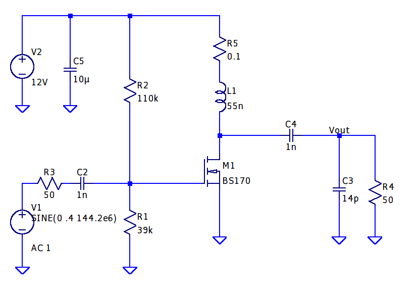
Since I do a lot of RF projects, I wanted to see if I could make a 2m power amplifier using a minimal set of components. I have a number of BS170 MOSFET transistors that I’ve used for dozens of applications over the years from guitar pedal pre-amps to digital control circuits. I started this project by building a class A amplifier on a bare piece of copper laminate. I was able to get 9 dB of gain with a power output of 15 dBm and a quiescent current of 83 mA. The schematic is shown below. R3 and R4 can be omitted if you happen to be building the circuit and replaced with 50 ohm SMA connectors. I used a variable cap at C3 to tune the circuit for maximum output power,
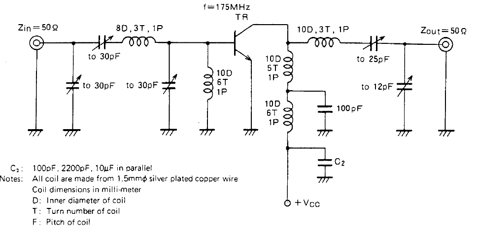
With 15 dBm of output power, I thought this would be adequate to drive a power amplifier stage. I nabbed some 2SC1970 transistors off eBay for a few bucks and started experimenting with the application circuit in the datasheet. This transistor is quite old by modern standards, but they were cheap and in a TO-220 package, so I figured they could take a beating. The standard application circuit was a good jumping off point for starting the design, and I was able to easily make changes to the air-core inductors by compressing and stretching the windings. I wound up just getting as close as I could with the inductors and relying on the variable capacitors in the circuit to get as much power as I could.
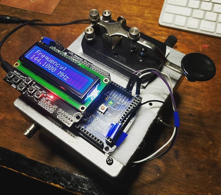
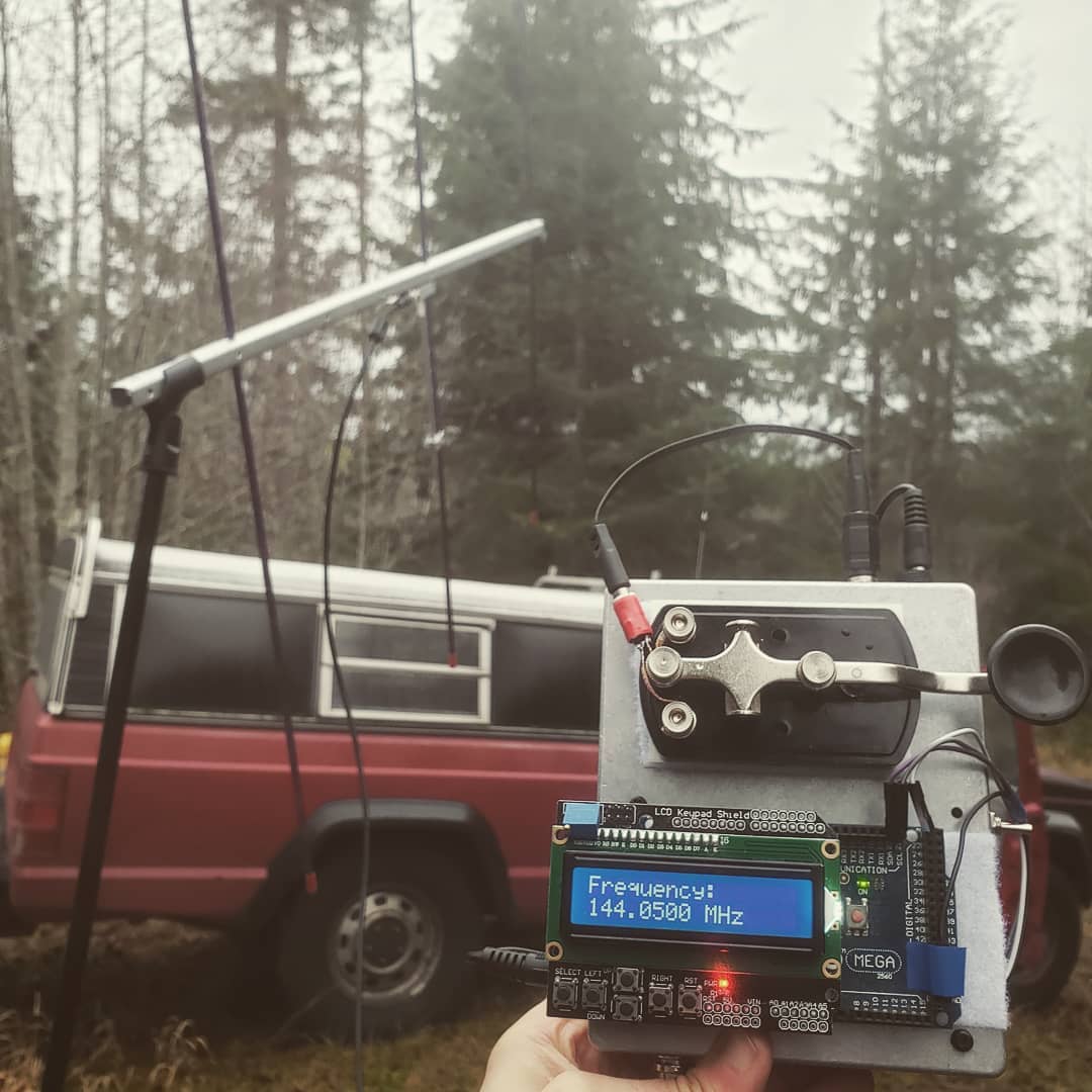
The LO portion of the transmitter was an Si5351 clock signal generator controlled by an ATMega2560 Arduino board. It’s able to get up to 160 MHz (200 MHz now in the Si5351B chips) and is programmed via an I2C port. I setup button 5 (Select) on the LCD shield to enable the LO later on, but I just had it running originally at startup and then connected the straight key in series with the 12V supply (widow-maker style) to the PA.
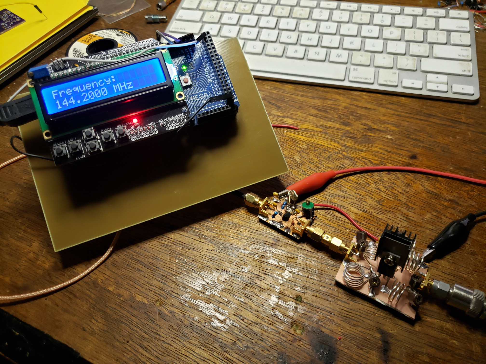
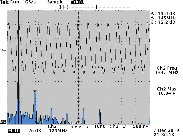
Above is the measured output on the old Tektronix TDS 360 oscilloscope. Measured power output is right at 1 watt. The second harmonic is a little higher than I would have liked, but an added LPF to the output should help fix that right up. The last thing to do was to get out in the rain in January and see if someone could pick it up. I hooked up a 3-element yagi to the output and the signal from the transmitter was picked up by W7YOZ in Shelton, WA some 22 miles to the north east.
Of course, here is the Arduino code for the RF signal generator using the Adafruit Si5351 clock generator board. The controls need to be incorporated into an interrupt trigger to make the thing more controllable, but it hasn’t been so annoying that I’ve needed to fix it as of yet. Just fair warning in case someone out there in the world decides to use it for anything.
// Arduino RF Signal Generator
// author: Abram Morphew
// date: 2019.04.25
#include <Wire.h>
#include <Adafruit_SI5351.h>
#include <LiquidCrystal.h>
Adafruit_SI5351 clockgen = Adafruit_SI5351();
LiquidCrystal lcd(8, 9, 4, 5, 6, 7);
long frequency = 144100000;
long inc = 1000;
char* data = "0";
int btn = 0;
bool keyPress = false;
bool enable = false;
void setup() {
lcd.begin(16,2);
lcd.print("Initialize");
delay(500);
/* Initialise the sensor */
if (clockgen.begin() != ERROR_NONE) {
lcd.print("Ooops, no Si5351 detected ... Check your wiring or I2C ADDR!");
while(1);
}
setfrequency(frequency);
delay(100);
lcd.clear();
}
void loop() {
if (keyPress == true) {
setfrequency(frequency);
keyPress = false;
}
// set title:
lcd.setCursor(0,0);
lcd.print("Frequency: ");
// update frequency
lcd.setCursor(0, 1);
lcd.print(frequency/1e6,3);
lcd.print(" MHz ");
btn = readkeypad();
if ((btn == 1) && (frequency + inc <= 155e6)) { frequency = frequency + inc; keyPress = true; delay(100); }
if ((btn == 2) && (frequency - inc >= 420e3)) { frequency = frequency - inc; keyPress = true; delay(100); }
if ((btn == 3) && (inc < 1e8)) { inc = inc * 10; delay(100); }
if ((btn == 4) && (inc > 1e4)) { inc = inc / 10; delay(100); }
if (btn == 5) {
clockgen.enableOutputs(true);
}
if (btn != 5) {
clockgen.enableOutputs(false);
}
delay(10);
}
int readkeypad(){
int adc_key_in = analogRead(0); //
int ret = 0;
if (adc_key_in < 50) ret = 4;
if ( (adc_key_in > 800) && (adc_key_in < 1150)) ret = 0;
if ( (adc_key_in > 80) && (adc_key_in < 150) ) ret = 1;
if ( (adc_key_in > 250) && (adc_key_in < 350) ) ret = 2;
if ( (adc_key_in > 400) && (adc_key_in < 500) ) ret = 3;
if ( (adc_key_in > 500) && (adc_key_in < 800) ) ret = 5;
//lcd.print(adc_key_in);
return ret;
}
int setfrequency(long frequency) {
int m = 0;
int n = 0;
int fs = 8;
clockgen.enableOutputs(false);
if (frequency > 55e6) {
fs = 8;
} else if ((frequency <= 55e6) && (frequency > 25e6)) {
fs = 16;
} else if ((frequency <= 25e6) && (frequency > 10e6)) {
fs = 32;
} else if ((frequency <= 10e6) && (frequency > 6e6)) {
fs = 64;
} else if ((frequency <= 6e6) && (frequency > 3e6)) {
fs = 128;
} else if ((frequency <= 6e6) && (frequency > 2.1e6)) {
fs = 256;
} else if ((frequency <= 2.1e6) && (frequency > 1e6)) {
fs = 512;
} else if (frequency <= 1e6) {
fs = 900;
}
// determine m, n, and d from frequency value
m = floor(frequency*fs/25e6);
n = ((frequency*fs/25e6) - m)*1000;
clockgen.setupPLL(SI5351_PLL_A, m, n, 1000);
clockgen.setupMultisynth(0, SI5351_PLL_A, fs, 0, 1);
}