Arduino: Audio Frequency Generator

Back in good ol’ 2012 (the year the world was supposed to end), I posted some code for a simple Arduino controlled low-frequency oscillator (LFO). It has made its way into some very interesting projects over the years, but recently I was asked in the comments if the code could be modified to have a wider frequency output up into the kHz range. I thought it was a good question, so I made the effort to see what the limitations could be.

How It Works

So, the original LFO employs timers on an ATMega328 (or ATTiny85 depending on which version of the code) to generate the audio output. By using a wave table of a basic sine wave stored in an array, one timer (TIMER0) winds up setting the sample rate by grabbing each sample from the array at a configured interval, and the other timer (TIMER2) creates a PWM output on the selected pin (pin 3 in the code). So by setting an 8-bit value on OCR0A, the sample rate can be adjusted which adjusts the frequency on the output of TIMER2. The datasheet for the ATMega328 gives the following formula for the frequency of the output compare register.

If we take this formula and divide it by the number of samples, we get the output frequency. That means that the output frequency can also be scaled by reducing the number of samples available. So, I made a big output table in LibreOffice and saw that an OCR0A value of 128 was twice the frequency from 255. At 255, I could reduce the number of output samples by half and sweep over the same sample rates but get an increase in output frequency. This introduced a method of frequency scaling. The trade-off, however, is that the sine wave on the output is much less sinusoidal being that it has lower resolution, and that introduces higher order harmonics thus changing the timbre of the sine wave.

Another thing to keep in mind is that the sample rate from the output PWM gets very low and even into the audio range itself. This means that some kind of audio filter is needed on the output. I put a first order low-pass filter using a 2.2k series resistor and a 10 uF capacitor to ground. This worked surprisingly well, though some of the sampling noise shows up on the output at very low frequencies. Being an 8-bit audio signal, this isn’t much to worry about in the grand scheme of things since. I also found that the noise on the output could be lowered by implementing a simple moving average filter in the code on the 10-bit ADC input of the rate control if using a potentiometer to set the frequency. With the timer prescalar set to 64, we should get 64 clock ticks before the next sample is grabbed, so this left some room for some calculations to happen in between sample changes.

It’s all pretty experimental, but it seems to work alright. The frequency range is from around 1 Hz up to 14 kHz (more or less). If you’re using a pot to control the rate, use a linear one as the frequency output gets very logarithmic towards the top of the range.

The Code

// Project: Arduino Audio Frequency Signal Generator
// Version: 1.0
// Author: Abram Morphew
// Date: 2021.10.12

#define cbi(sfr, bit) (_SFR_BYTE(sfr) &= ~_BV(bit))
#define sbi(sfr, bit) (_SFR_BYTE(sfr) |= _BV(bit))

uint8_t sineTable256[] = {
  128,131,134,137,140,143,146,149,152,155,158,162,165,167,170,173,
  176,179,182,185,188,190,193,196,198,201,203,206,208,211,213,215,
  218,220,222,224,226,228,230,232,234,235,237,238,240,241,243,244,
  245,246,248,249,250,250,251,252,253,253,254,254,254,255,255,255,
  255,255,255,255,254,254,254,253,253,252,251,250,250,249,248,246,
  245,244,243,241,240,238,237,235,234,232,230,228,226,224,222,220,
  218,215,213,211,208,206,203,201,198,196,193,190,188,185,182,179,
  176,173,170,167,165,162,158,155,152,149,146,143,140,137,134,131,
  128,124,121,118,115,112,109,106,103,100,97,93,90,88,85,82,
  79,76,73,70,67,65,62,59,57,54,52,49,47,44,42,40,
  37,35,33,31,29,27,25,23,21,20,18,17,15,14,12,11,
  10,9,7,6,5,5,4,3,2,2,1,1,1,0,0,0,
  0,0,0,0,1,1,1,2,2,3,4,5,5,6,7,9,
  10,11,12,14,15,17,18,20,21,23,25,27,29,31,33,35,
  37,40,42,44,47,49,52,54,57,59,62,65,67,70,73,76,
  79,82,85,88,90,93,97,100,103,106,109,112,115,118,121,124
};

uint8_t sineTable128[] = {
  128,134,140,146,152,158,165,170,176,182,188,193,198,203,208,213,
  218,222,226,230,234,237,240,243,245,248,250,251,253,254,254,255,
  255,255,254,254,253,251,250,248,245,243,240,237,234,230,226,222,
  218,213,208,203,198,193,188,182,176,170,165,158,152,146,140,134,
  128,121,115,109,103,97,90,85,79,73,67,62,57,52,47,42,
  37,33,29,25,21,18,15,12,10,7,5,4,2,1,1,0,
  0,0,1,1,2,4,5,7,10,12,15,18,21,25,29,33,
  37,42,47,52,57,62,67,73,79,85,90,97,103,109,115,121 };
  
uint8_t sineTable64[] = {
  128,140,152,165,176,188,198,208,218,226,234,240,245,250,253,254,
  255,254,253,250,245,240,234,226,218,208,198,188,176,165,152,140,
  128,115,103,90,79,67,57,47,37,29,21,15,10,5,2,1,
  0,1,2,5,10,15,21,29,37,47,57,67,79,90,103,115
};

uint8_t sineTable32[] = {
  128,152,176,198,218,234,245,253,255,253,245,234,218,198,176,152,
  128,103,79,57,37,21,10,2,0,2,10,21,37,57,79,103,
};

uint8_t sineTable16[] = {
  128,176,218,245,255,245,218,176,128,79,37,10,0,10,37,79
};

uint8_t sineTable8[] = {
  128,218,255,218,128,37,0,37,128
};

uint8_t sineTable4[] = {
  128,255,128,0,128
};

uint8_t sineTable2[] = {
  255,0
};

uint8_t tWave = 128;
uint8_t sWave = 255;
uint8_t ruWave = 128;
uint8_t rdWave = 128;
uint8_t rWave = 128;
uint8_t inc = 1;
uint8_t r = 0;

int   n = 32;        // number of averages for ADC input (should be a power of 2: 32 max)
int   ocr[32] = {};
int   i = 0;
int   t = 0;    // time delay index for rate sweep
int   sweep = 1023;    // sweep
int   rate = 0;
int   waveform;
byte  d = HIGH;
byte  down = LOW;    // increase freq if LOW, decrease freq if HIGH
byte  rateSelectPin = 1;
byte  waveSelectPin = 0;

void setup() {
  pinMode(waveSelectPin, INPUT);
  pinMode(rateSelectPin, INPUT);
  pinMode(3, OUTPUT);
  setupTimer();
  OCR0A = 128;
}

void loop() {
  // -- Waveform Selection
  waveform = map(analogRead(waveSelectPin),0,1023,1,7);
  //waveform = 1;
  
  // -- Frequency Selection with ADC pin 1
  if (r >= n) r = 0;
  ocr[r] = map(analogRead(rateSelectPin),0,1023,1015,3);
  r++;
  
  // -- ADC input averaging
  for(uint8_t c = 0; c < n; c++) { rate += ocr[c]; }  
  rate = floor(rate / n);
  
  // Uncomment for frequency sweep
  /*--------------------
  if (t >= 2048) {
    sweep--;
    t = 0;
  }
  
  if (sweep <= 4) {
    sweep = 1023;
  }
  t++;
  rate = sweep;
  //----------------------- */

  // rate scaling with increasing frequency
  if (rate < 128) {
    inc = 128;
    rate = rate * 2;
  } else if ((128 <= rate) && (rate < 256)) {
    inc = 64;
    rate = rate;
  } else if ((256 <= rate) && (rate < 384)) {
    inc = 32;
    rate = rate - 128;
  } else if ((384 <= rate) && (rate < 512)) {
    inc = 16;
    rate = rate - 256;
  } else if ((512 <= rate) && (rate < 640)) {
    inc = 8;
    rate = rate - 384;
  } else if ((640 <= rate) && (rate < 768)) {
    inc = 4;
    rate = rate - 512;
  } else if ((768 <= rate) && (rate < 896)) {
    inc = 2;
    rate = rate - 640;
  } else if ((896 <= rate) && (rate < 1024)) {
    inc = 1;
    rate = rate - 768;
  }  
  
  OCR0A = rate;
}

ISR(TIMER0_COMPA_vect) {
  if(i >= (256 / inc)) i = 0;
  switch(waveform) {
    case 1:
      OCR2B = sine(i, inc);      
    break;
    case 2:
      OCR2B = triangle(i);
    break;
    case 3:
      OCR2B = square(i);
    break;
    case 4:
      OCR2B = rampUp(i);
    break;
    case 5:
      OCR2B = rampDown(i);
    break;
    case 6:
      OCR2B = rand(i);
    break;
    case 7:
      OCR2B = white(i);
    break;
  }
  i++;
}

void setupTimer() {
  cli();
/*--- TIMER2 CONFIG ---*/
  sbi(TCCR2A,WGM20);
  sbi(TCCR2A,WGM21);
  cbi(TCCR2A,WGM22);
 
  sbi(TCCR2A,COM2B1);
  cbi(TCCR2A,COM2B0); 
 
  sbi(TCCR2B, CS20);
  cbi(TCCR2B, CS21);
  cbi(TCCR2B, CS22);
   
 /*--- TIMER0 CONFIG ---*/ 
  sbi(TCCR0B,CS00);
  sbi(TCCR0B,CS01);
  cbi(TCCR0B,CS02);

  sbi(TCCR0A, COM0A1);
  cbi(TCCR0A, COM0A0);
    
  cbi(TCCR0A, WGM00);
  sbi(TCCR0A, WGM01);
  cbi(TCCR0A, WGM02);

  cbi(TIFR0,OCF0A);
  sbi(TIMSK0,OCIE0A);
  sei(); 
}

int sine(int i, int inc) {
  if (inc == 1) {
    return sineTable256[i];
  } else if (inc == 2) {
    return sineTable128[i];
  } else if (inc == 4) {
    return sineTable64[i];
  } else if (inc == 8) {
    return sineTable32[i];
  } else if (inc == 16) {
    return sineTable16[i];
   } else if (inc == 32) {
    return sineTable8[i];
  } else if (inc == 64) {
    return sineTable4[i];
  } else if (inc == 128) {
    return sineTable2[i];
  }
}

int triangle(int i) {
  if(tWave >= 255) d = LOW;
  if(tWave <= 0) d = HIGH;
  if(d == HIGH) tWave = tWave + inc;
  if(d == LOW) tWave = tWave + inc;
  return tWave; 
}

int rampUp(int i) {
  ruWave = ruWave + inc;
  if(ruWave > 255) ruWave = 0; 
  return ruWave;
}

int rampDown(int i) {
  rdWave = rdWave + inc;
  if(rdWave < 0) rdWave = 255;
  return rdWave;
}

int square(int i) {
  if(i >= (128 / inc)) sWave = 255;
  if(i < (128/inc)) sWave = 0;
  return sWave;
}

int rand(int i) {
  if(i == (rWave / inc)) rWave = random(255);
  return rWave;
}

int white(int i) {
  return random(255);
}

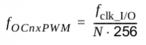
Arduino: 1-Watt 2m Transmitter with RF Signal Generator

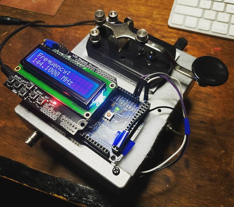
Since I do a lot of RF projects, I wanted to see if I could make a 2m power amplifier using a minimal set of components. I have a number of BS170 MOSFET transistors that I’ve used for dozens of applications over the years from guitar pedal pre-amps to digital control circuits. I started this project by building a class A amplifier on a bare piece of copper laminate. I was able to get 9 dB of gain with a power output of 15 dBm and a quiescent current of 83 mA. The schematic is shown below. R3 and R4 can be omitted if you happen to be building the circuit and replaced with 50 ohm SMA connectors. I used a variable cap at C3 to tune the circuit for maximum output power,

With 15 dBm of output power, I thought this would be adequate to drive a power amplifier stage. I nabbed some 2SC1970 transistors off eBay for a few bucks and started experimenting with the application circuit in the datasheet. This transistor is quite old by modern standards, but they were cheap and in a TO-220 package, so I figured they could take a beating. The standard application circuit was a good jumping off point for starting the design, and I was able to easily make changes to the air-core inductors by compressing and stretching the windings. I wound up just getting as close as I could with the inductors and relying on the variable capacitors in the circuit to get as much power as I could.

The LO portion of the transmitter was an Si5351 clock signal generator controlled by an ATMega2560 Arduino board. It’s able to get up to 160 MHz (200 MHz now in the Si5351B chips) and is programmed via an I2C port. I setup button 5 (Select) on the LCD shield to enable the LO later on, but I just had it running originally at startup and then connected the straight key in series with the 12V supply (widow-maker style) to the PA.

Above is the measured output on the old Tektronix TDS 360 oscilloscope. Measured power output is right at 1 watt. The second harmonic is a little higher than I would have liked, but an added LPF to the output should help fix that right up. The last thing to do was to get out in the rain in January and see if someone could pick it up. I hooked up a 3-element yagi to the output and the signal from the transmitter was picked up by W7YOZ in Shelton, WA some 22 miles to the north east.

Of course, here is the Arduino code for the RF signal generator using the Adafruit Si5351 clock generator board. The controls need to be incorporated into an interrupt trigger to make the thing more controllable, but it hasn’t been so annoying that I’ve needed to fix it as of yet. Just fair warning in case someone out there in the world decides to use it for anything.

// Arduino RF Signal Generator
// author: Abram Morphew
// date: 2019.04.25

#include <Wire.h>
#include <Adafruit_SI5351.h>
#include <LiquidCrystal.h>

Adafruit_SI5351 clockgen = Adafruit_SI5351();
LiquidCrystal lcd(8, 9, 4, 5, 6, 7);

long frequency = 144100000;
long inc = 1000;
char* data = "0";
int btn = 0;
bool keyPress = false;
bool enable = false;

void setup() {
  lcd.begin(16,2);
  lcd.print("Initialize");
  delay(500);
  
  /* Initialise the sensor */
  if (clockgen.begin() != ERROR_NONE) {
    lcd.print("Ooops, no Si5351 detected ... Check your wiring or I2C ADDR!");
    while(1);
  }

  setfrequency(frequency);
  delay(100);
  lcd.clear();
  
}

void loop() {
  if (keyPress == true) {
    setfrequency(frequency);
    keyPress = false;
  }
  
  // set title:
  lcd.setCursor(0,0);
  lcd.print("Frequency: ");

  // update frequency 
  lcd.setCursor(0, 1);
  lcd.print(frequency/1e6,3);
  lcd.print(" MHz ");

  btn = readkeypad();
  if ((btn == 1) &amp;&amp; (frequency + inc &lt;= 155e6)) { frequency = frequency + inc; keyPress = true; delay(100); }
  if ((btn == 2) &amp;&amp; (frequency - inc &gt;= 420e3)) { frequency = frequency - inc; keyPress = true; delay(100); }

  if ((btn == 3) &amp;&amp; (inc &lt; 1e8)) { inc = inc * 10; delay(100); }
  if ((btn == 4) &amp;&amp; (inc &gt; 1e4)) { inc = inc / 10; delay(100); } 
  if (btn == 5) {
    clockgen.enableOutputs(true);
  }  
  
  if (btn != 5) {
    clockgen.enableOutputs(false);
  }
  
  delay(10);
}

int readkeypad(){
      int adc_key_in = analogRead(0); //
      int ret = 0;

      if (adc_key_in &lt; 50) ret = 4;
      if ( (adc_key_in &gt; 800) &amp;&amp; (adc_key_in &lt; 1150)) ret = 0;
      if ( (adc_key_in &gt;  80) &amp;&amp; (adc_key_in &lt; 150) ) ret = 1;
      if ( (adc_key_in &gt; 250) &amp;&amp; (adc_key_in &lt; 350) ) ret = 2;
      if ( (adc_key_in &gt; 400) &amp;&amp; (adc_key_in &lt; 500) ) ret = 3;
      if ( (adc_key_in &gt; 500) &amp;&amp; (adc_key_in &lt; 800) ) ret = 5;
  
      
      //lcd.print(adc_key_in);
      return ret;
 }

int setfrequency(long frequency) {
  int m = 0;
  int n = 0;
  int fs = 8;
  clockgen.enableOutputs(false);

  if (frequency &gt; 55e6) {
    fs = 8;
  } else if ((frequency &lt;= 55e6) &amp;&amp; (frequency &gt; 25e6)) {
    fs = 16;
  } else if ((frequency &lt;= 25e6) &amp;&amp; (frequency &gt; 10e6)) {
    fs = 32;
  } else if ((frequency &lt;= 10e6) &amp;&amp; (frequency &gt; 6e6)) {
    fs = 64;
  } else if ((frequency &lt;= 6e6) &amp;&amp; (frequency &gt; 3e6)) {
    fs = 128;
  } else if ((frequency &lt;= 6e6) &amp;&amp; (frequency &gt; 2.1e6)) {
    fs = 256;
  } else if ((frequency &lt;= 2.1e6) &amp;&amp; (frequency &gt; 1e6)) {
    fs = 512;
  } else if (frequency &lt;= 1e6) {
    fs = 900;
  }

  // determine m, n, and d from frequency value
  m = floor(frequency*fs/25e6);
  n = ((frequency*fs/25e6) - m)*1000;
  clockgen.setupPLL(SI5351_PLL_A, m, n, 1000);
  clockgen.setupMultisynth(0, SI5351_PLL_A, fs, 0, 1);
}

ngSpice: single frequency FM modulated signal generation

ever wanted to see how that 2N2222 might hold up as a linear RF amplifier? here’s a handy feature of ngSpice that i found recently. i’m rather new to ngSpice and at first was somewhat frustrated by its differences from other SPICE variants. however, i’ve earned a deep appreciation for it and its integration with the gEDA suite.

V1 n1 0 sffm(2 24 10k 5 1k)
.tran 0.01ms 2ms
.plot n1

the above code generates the waveform seen above. the corresponding values in the sffm() function run something like this.

Parameters Default value Unit
Vo (offset) Ampere or Volt
Va (amplitude) Ampere or Volt
Fc (carrier frequency) 1/Tstop Hz (Hertz)
Mi (modulation index)
Fs (modulation frequency) 1/Tstop Hz (Hertz)