Basic Voltage-Controlled Amplifier

I’ve been looking at the theoretical principles that govern the voltage-controlled amplifier (VCA) recently and came across some simple VCA designs that caught my attention. A common technique involves a JFET and an opamp to achieve VCA type operation by using the JFET as a voltage-controlled resistor somewhere in the input path. I’ve seen a good deal of these circuits out there, but I had trouble getting good simulation results from what I had seen. I cam across an article by Rod Elliot of Elliot Sound Products which covered some nice history and interesting discussion of the VCA in general. After going over the information there, I came up with this design based on some of the more basic designs presented.

Basic VCA LTSpice Schematic

One of the things I’ve been most interested in is trying to accomplish this with a single supply which is common in most stompbox setups. In the schematic, there’s an emitter-follower stage just to act as a buffer for the input signal followed by an inverting opamp stage. To make this work, both C1 and C2 are required to effectively AC couple both input signals (Vin and Vctl) to the opamp stage. There’s an RC network that is supposed to tame the distortion in the output by taking a portion of the output and connecting it to the input of the J201. The article explains this in decent detail. In simulation, the it seems to smooth out the non-linearity of the JFET as Vctl changes. Using the J201, LTSpice gives a decent linear-like response over a range of around 500 mV (0 to -500 mV at the input) and operates decently with a 500 mVp signal.

VCA Linearity Test

For use with an LFO, I found that the best results happen with a slight negative voltage offset and a signal who’s amplitude peaks at 0V (i.e. 250 mV sinusoidal signal with a -250 mV offset). Of course, this is all highly dependent on the threshold voltage of the J201 which can range from -0.3 V to -1.5 V according to the Fairchild datasheet. It will be interesting to see the results of this circuit on a breadboard.

LFO modulated VCA Simulation

References:
[1] Gray, P. (2009). Analysis and design of analog integrated circuits. New York: Wiley.

[2] Sound.whsites.net. (2017). VCAs. [online] Available at: http://sound.whsites.net/articles/vca-techniques.html [Accessed 1 Sep. 2017].

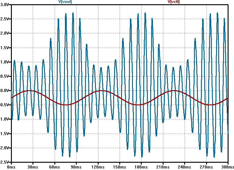
LFO modulated simple VCF

lfo_vcf_rev_aa001

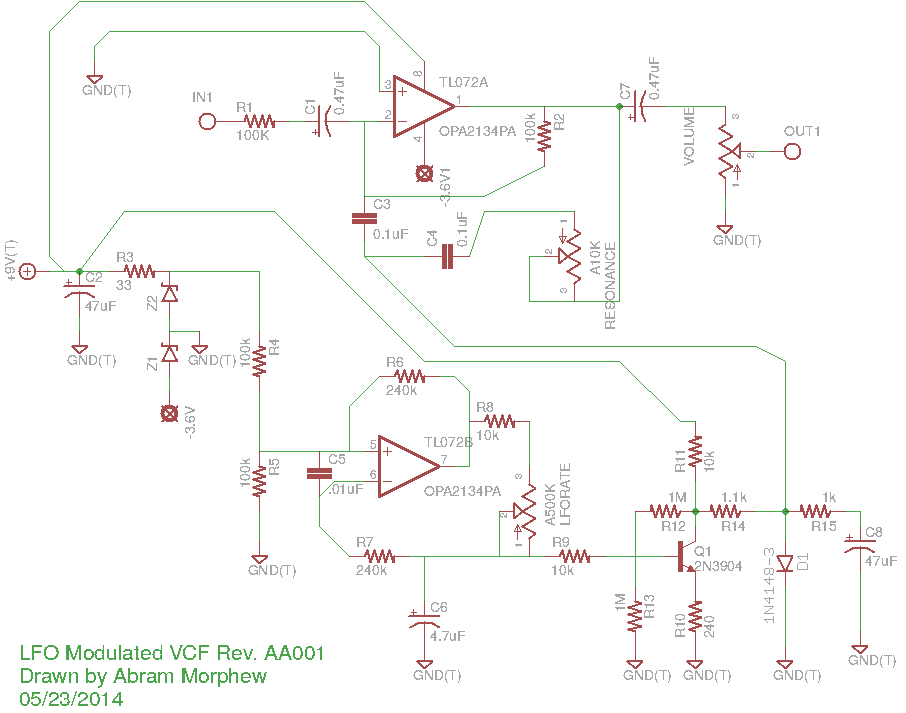
this is a rough draft of a circuit i’ve been working on based of the Simple VCF circuit floating out there. a big thanks to the original author for that. i’m sure there are some mistakes in here. it’s an odd one for sure, but it works on the breadboard. the opamp is a TL072. square-wave input from the generator comes out pretty sine-wave like which is what is desired. the output is a little noisy, but i will work that out with time.

solid-state tremolo for tube amps…

i’ve have a CBS-era Fender Bantam Bass in for repair that looks like a bowl of spaghetti inside the chassis. it’s a slew of yellow wire spread from one side to the other that resembles the web of a drunken spider. the amp has been modified to include a tremolo, reverb, and an effects loop that replaces the bass channel in the amp. the tremolo circuit was originally a Weber kit, but someone ripped a couple of the pads off the PCB while trying to modify the mod. i just redesigned a tremolo circuit based upon a simple dual opamp LFO using the Weber’s rectifier as a guide to get voltage from the heater filament supply. i attached the output to an “Intensity” pot and wired it into the cathode of the second half of the initial 12AX7. The schematic below has node “A” highlighted to show where the output of the tremolo circuit was connect in the amplifier.

bantam_layout_01

this is the layout as i was laying my new designed tremolo into the existing circuit.

bantam_layout_02

this is the part of the original Weber tremolo where the last tech (careful with that soldering iron, Eugene!) attempted to modulate of the negative grid bias. though a sound idea, the circuit itself wound up acting more like a compression effect by changing altering the bias when signal was present. also, a solid-state tremolo like this won’t have much of an overall effect on negative grid biasing due mostly to it’s weak output. rails on the LFO is roughly +5.5V resulting in a good 2.25Vpk (1.5Vrms) signal which is hardly enough to be noticeable. i also tend to avoid using trem circuits that re-bias the output stage simply because it does seem to put undue stress on the tubes and surrounding components. it seems more efficient and makes more sense to me to modulate signals while they’re still small.

bantam_layout_04

cleaner and a little more manageable.

bantam_layout_05

and with a fine custom-made panel, the old Bantam looks and sounds more like a ’65 Super Reverb than ever before. granted, not all steps were taken to black-face the amp, but a few value substitutions were made to achieve more of a black-face tone.

TDA2040-based amp schematic with EQ…

well here’s the first draft of the simplest medium powered solid state design i could muster. TL082 can easily be substituted with a TL072 which is probably better anyhow (i just have all these TL082s laying around). the power supply i’m using more like 14-15V. both ICs should easily be able to handle up to 20V and that would allow for louder operation, but i think 15V is safe. all the resistors are 1/8W minus R20 which is 1/4W.