Tag: oscillator
-
Arduino: Audio Frequency Generator
Back in good ol’ 2012 (the year the world was supposed to end), I posted some code for a simple Arduino controlled low-frequency oscillator (LFO). It has made its way into some very interesting projects over the years, but recently I was asked in the comments if the code could be modified to have a…
-
7MHz Crystal Oscillator Design
After constructing a 40m wire dipole that works with my SDR setup, I needed to start working on a transmission system. At the heart of virtually any RF system lies a stable oscillator, and crystal oscillators are ubiquitous in many low-power (QRP) rigs simply because they are so stable. After some rough math and a…
-
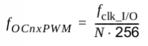
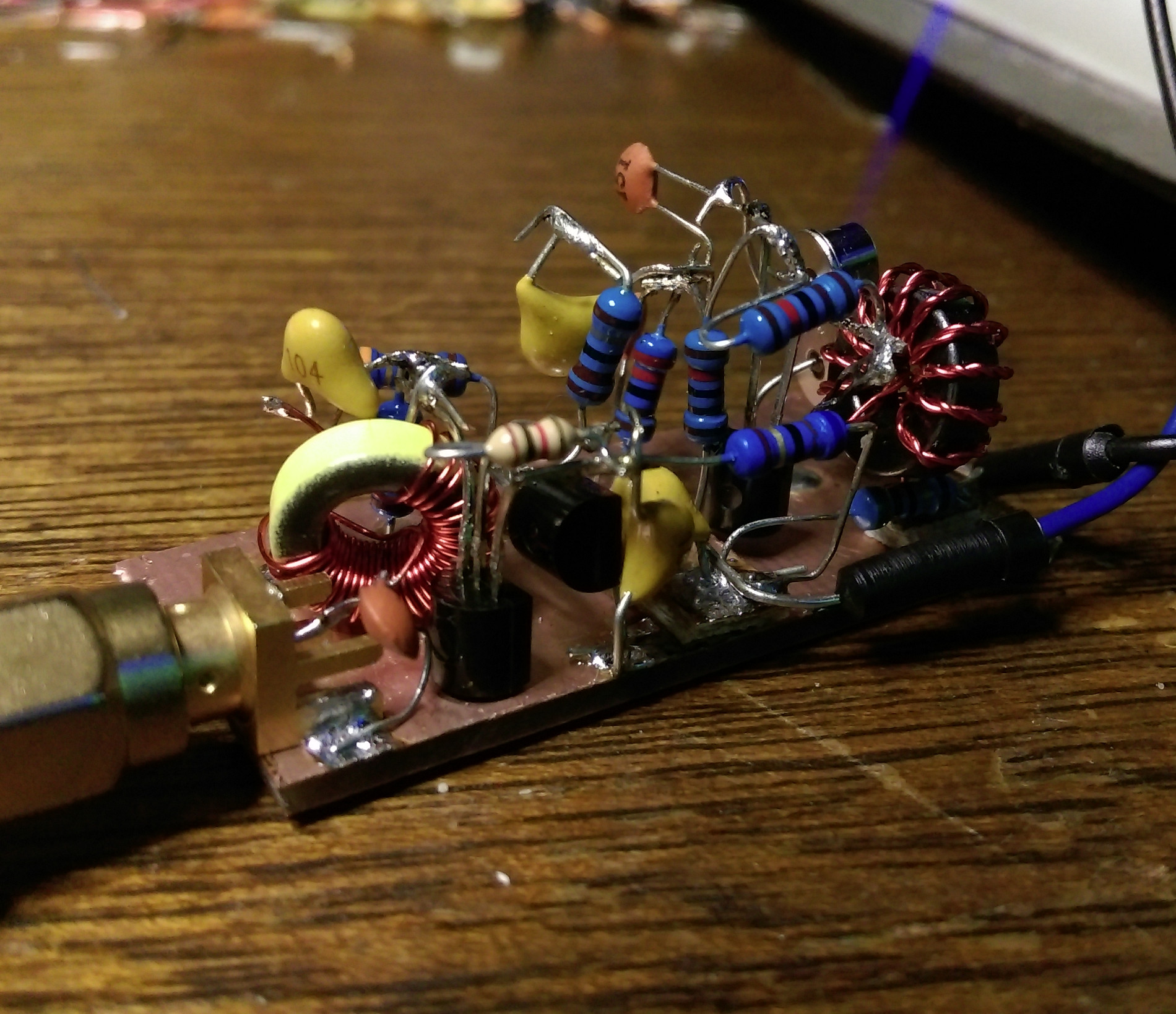
2m AM Exciter
Here’s a project that I’ve been working on for a class recently. This is a very basic 2m AM Transmitter that operates from 144.25 to 144.31 MHz. It does put out a low powered RF signal (around 5 mW PEP) that has been copied over 1 mile from the transmitter. This is an ongoing project…
-
simple phase shift oscillator…
a practice in designing an oscillator. this particular circuit employs a 2N2222A transistor on 6 volts. i used this Electronic-Tutorials.ws page to design the circuit. there were many reasons for this experiment, but the most immediate was to act as a simple CW practice oscillator. the final circuit looks something like the following.
-
Square-wave Oscillator Meets PT2399…
Square-wave Oscillator with PT2399… from abram on Vimeo. Very short video of the waveform captured using Xoscpe of the PT2399 applied to the LM386 square-wave oscillator. Sorry for the bad focusing. I was in a rush. I just needed a visual capture for later analysis. [audio:http://abrammorphew.com/notes/wp-content/uploads/2011/06/osc_delay.mp3|titles=i just broke the gameboy] …and here’s a clip of…
-
LM386 Square-wave Oscillator
Here’s a small LM386-based square-wave oscillator built from the following schematic. I replaced the 30k resistor with a 50k Potentiometer from my stash of parts which then, of course, acts as a pitch controller. The following audio is some track recordings made in Ableton 8.0 with a little filter on one track and some reverb…