After constructing a 40m wire dipole that works with my SDR setup, I needed to start working on a transmission system. At the heart of virtually any RF system lies a stable oscillator, and crystal oscillators are ubiquitous in many low-power (QRP) rigs simply because they are so stable. After some rough math and a lot of simulations in LTSpice, I came up with this design to give me somewhere around 7 dBm of power.
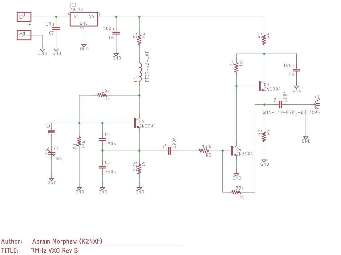
The first stage is simple Colpitts oscillator topology with a “bent” 7.03 MHz crystal resonator. The 30 pF variable capacitor (C1) provides around 2 kHz of tuning. The output stage is a common-collector (Q4) and emitter-follower (Q3) with a negative feedback loop. I forget exactly where I saw this configuration, but I thought I would try it out and see if it worked. As you might have guessed, the output is loaded with higher order harmonics resulting in a waveform that doesn’t resemble a sine wave at all. I made sure to include a simple second-order low-pass Butterworth filter on the output to filter the output.
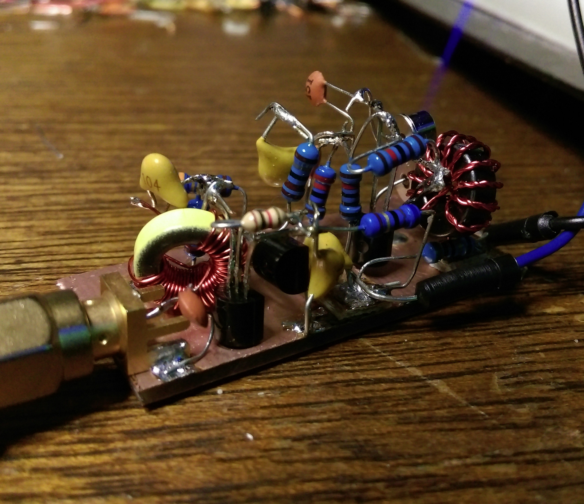
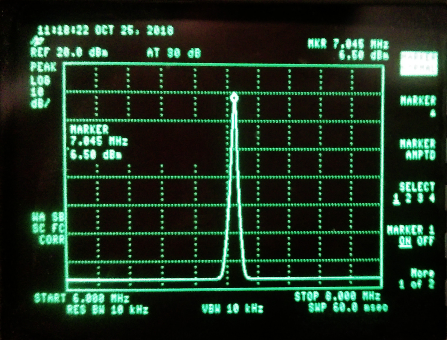
Pictured above is the ugly constructed version of the oscillator in all it’s dead-bug style. I built it on a scrap piece of double-sided FR4 and overall it’s performance came out fairly close to what LTSpice had predicted. I got around 6 dBm of output and the second harmonic is around 29 dB down (around -23 dBm). That’s not the cleanest of signals, but it’s about right for the filter. Below is the output shown on my HP 8595E spectrum analyzer.
For the next phase, I’ll likely be adding control of the oscillator via an ATTiny chip. This will give me the ability to automate on-off keying of the device turning it into a simple CW beacon. One thing that could be improved is the current draw (~40 mA) from the emitter-follower at Q3. Basically, it’s a class A amplifier so it’s not the most efficient design in the world, but it provides enough power for driving an ADE-1 and could run off a small solar panel if I wanted to use it in the field.