Linux Audio Production: Getting started with Jack and MIDI

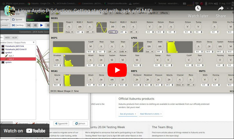
Last year, I posted this quick tutorial on the SMBA YouTube channel walking through the steps to use a MIDI controller with Jack using Xubuntu 20.04. I am posting it hear just for the sake of consistency and good housekeeping. Hopefully, I’ll get to make some more of these soon.

Arduino: Audio Frequency Generator

Back in good ol’ 2012 (the year the world was supposed to end), I posted some code for a simple Arduino controlled low-frequency oscillator (LFO). It has made its way into some very interesting projects over the years, but recently I was asked in the comments if the code could be modified to have a wider frequency output up into the kHz range. I thought it was a good question, so I made the effort to see what the limitations could be.

How It Works

So, the original LFO employs timers on an ATMega328 (or ATTiny85 depending on which version of the code) to generate the audio output. By using a wave table of a basic sine wave stored in an array, one timer (TIMER0) winds up setting the sample rate by grabbing each sample from the array at a configured interval, and the other timer (TIMER2) creates a PWM output on the selected pin (pin 3 in the code). So by setting an 8-bit value on OCR0A, the sample rate can be adjusted which adjusts the frequency on the output of TIMER2. The datasheet for the ATMega328 gives the following formula for the frequency of the output compare register.

If we take this formula and divide it by the number of samples, we get the output frequency. That means that the output frequency can also be scaled by reducing the number of samples available. So, I made a big output table in LibreOffice and saw that an OCR0A value of 128 was twice the frequency from 255. At 255, I could reduce the number of output samples by half and sweep over the same sample rates but get an increase in output frequency. This introduced a method of frequency scaling. The trade-off, however, is that the sine wave on the output is much less sinusoidal being that it has lower resolution, and that introduces higher order harmonics thus changing the timbre of the sine wave.

Another thing to keep in mind is that the sample rate from the output PWM gets very low and even into the audio range itself. This means that some kind of audio filter is needed on the output. I put a first order low-pass filter using a 2.2k series resistor and a 10 uF capacitor to ground. This worked surprisingly well, though some of the sampling noise shows up on the output at very low frequencies. Being an 8-bit audio signal, this isn’t much to worry about in the grand scheme of things since. I also found that the noise on the output could be lowered by implementing a simple moving average filter in the code on the 10-bit ADC input of the rate control if using a potentiometer to set the frequency. With the timer prescalar set to 64, we should get 64 clock ticks before the next sample is grabbed, so this left some room for some calculations to happen in between sample changes.

It’s all pretty experimental, but it seems to work alright. The frequency range is from around 1 Hz up to 14 kHz (more or less). If you’re using a pot to control the rate, use a linear one as the frequency output gets very logarithmic towards the top of the range.

The Code

// Project: Arduino Audio Frequency Signal Generator
// Version: 1.0
// Author: Abram Morphew
// Date: 2021.10.12

#define cbi(sfr, bit) (_SFR_BYTE(sfr) &= ~_BV(bit))
#define sbi(sfr, bit) (_SFR_BYTE(sfr) |= _BV(bit))

uint8_t sineTable256[] = {
  128,131,134,137,140,143,146,149,152,155,158,162,165,167,170,173,
  176,179,182,185,188,190,193,196,198,201,203,206,208,211,213,215,
  218,220,222,224,226,228,230,232,234,235,237,238,240,241,243,244,
  245,246,248,249,250,250,251,252,253,253,254,254,254,255,255,255,
  255,255,255,255,254,254,254,253,253,252,251,250,250,249,248,246,
  245,244,243,241,240,238,237,235,234,232,230,228,226,224,222,220,
  218,215,213,211,208,206,203,201,198,196,193,190,188,185,182,179,
  176,173,170,167,165,162,158,155,152,149,146,143,140,137,134,131,
  128,124,121,118,115,112,109,106,103,100,97,93,90,88,85,82,
  79,76,73,70,67,65,62,59,57,54,52,49,47,44,42,40,
  37,35,33,31,29,27,25,23,21,20,18,17,15,14,12,11,
  10,9,7,6,5,5,4,3,2,2,1,1,1,0,0,0,
  0,0,0,0,1,1,1,2,2,3,4,5,5,6,7,9,
  10,11,12,14,15,17,18,20,21,23,25,27,29,31,33,35,
  37,40,42,44,47,49,52,54,57,59,62,65,67,70,73,76,
  79,82,85,88,90,93,97,100,103,106,109,112,115,118,121,124
};

uint8_t sineTable128[] = {
  128,134,140,146,152,158,165,170,176,182,188,193,198,203,208,213,
  218,222,226,230,234,237,240,243,245,248,250,251,253,254,254,255,
  255,255,254,254,253,251,250,248,245,243,240,237,234,230,226,222,
  218,213,208,203,198,193,188,182,176,170,165,158,152,146,140,134,
  128,121,115,109,103,97,90,85,79,73,67,62,57,52,47,42,
  37,33,29,25,21,18,15,12,10,7,5,4,2,1,1,0,
  0,0,1,1,2,4,5,7,10,12,15,18,21,25,29,33,
  37,42,47,52,57,62,67,73,79,85,90,97,103,109,115,121 };
  
uint8_t sineTable64[] = {
  128,140,152,165,176,188,198,208,218,226,234,240,245,250,253,254,
  255,254,253,250,245,240,234,226,218,208,198,188,176,165,152,140,
  128,115,103,90,79,67,57,47,37,29,21,15,10,5,2,1,
  0,1,2,5,10,15,21,29,37,47,57,67,79,90,103,115
};

uint8_t sineTable32[] = {
  128,152,176,198,218,234,245,253,255,253,245,234,218,198,176,152,
  128,103,79,57,37,21,10,2,0,2,10,21,37,57,79,103,
};

uint8_t sineTable16[] = {
  128,176,218,245,255,245,218,176,128,79,37,10,0,10,37,79
};

uint8_t sineTable8[] = {
  128,218,255,218,128,37,0,37,128
};

uint8_t sineTable4[] = {
  128,255,128,0,128
};

uint8_t sineTable2[] = {
  255,0
};

uint8_t tWave = 128;
uint8_t sWave = 255;
uint8_t ruWave = 128;
uint8_t rdWave = 128;
uint8_t rWave = 128;
uint8_t inc = 1;
uint8_t r = 0;

int   n = 32;        // number of averages for ADC input (should be a power of 2: 32 max)
int   ocr[32] = {};
int   i = 0;
int   t = 0;    // time delay index for rate sweep
int   sweep = 1023;    // sweep
int   rate = 0;
int   waveform;
byte  d = HIGH;
byte  down = LOW;    // increase freq if LOW, decrease freq if HIGH
byte  rateSelectPin = 1;
byte  waveSelectPin = 0;

void setup() {
  pinMode(waveSelectPin, INPUT);
  pinMode(rateSelectPin, INPUT);
  pinMode(3, OUTPUT);
  setupTimer();
  OCR0A = 128;
}

void loop() {
  // -- Waveform Selection
  waveform = map(analogRead(waveSelectPin),0,1023,1,7);
  //waveform = 1;
  
  // -- Frequency Selection with ADC pin 1
  if (r >= n) r = 0;
  ocr[r] = map(analogRead(rateSelectPin),0,1023,1015,3);
  r++;
  
  // -- ADC input averaging
  for(uint8_t c = 0; c < n; c++) { rate += ocr[c]; }  
  rate = floor(rate / n);
  
  // Uncomment for frequency sweep
  /*--------------------
  if (t >= 2048) {
    sweep--;
    t = 0;
  }
  
  if (sweep <= 4) {
    sweep = 1023;
  }
  t++;
  rate = sweep;
  //----------------------- */

  // rate scaling with increasing frequency
  if (rate < 128) {
    inc = 128;
    rate = rate * 2;
  } else if ((128 <= rate) && (rate < 256)) {
    inc = 64;
    rate = rate;
  } else if ((256 <= rate) && (rate < 384)) {
    inc = 32;
    rate = rate - 128;
  } else if ((384 <= rate) && (rate < 512)) {
    inc = 16;
    rate = rate - 256;
  } else if ((512 <= rate) && (rate < 640)) {
    inc = 8;
    rate = rate - 384;
  } else if ((640 <= rate) && (rate < 768)) {
    inc = 4;
    rate = rate - 512;
  } else if ((768 <= rate) && (rate < 896)) {
    inc = 2;
    rate = rate - 640;
  } else if ((896 <= rate) && (rate < 1024)) {
    inc = 1;
    rate = rate - 768;
  }  
  
  OCR0A = rate;
}

ISR(TIMER0_COMPA_vect) {
  if(i >= (256 / inc)) i = 0;
  switch(waveform) {
    case 1:
      OCR2B = sine(i, inc);      
    break;
    case 2:
      OCR2B = triangle(i);
    break;
    case 3:
      OCR2B = square(i);
    break;
    case 4:
      OCR2B = rampUp(i);
    break;
    case 5:
      OCR2B = rampDown(i);
    break;
    case 6:
      OCR2B = rand(i);
    break;
    case 7:
      OCR2B = white(i);
    break;
  }
  i++;
}

void setupTimer() {
  cli();
/*--- TIMER2 CONFIG ---*/
  sbi(TCCR2A,WGM20);
  sbi(TCCR2A,WGM21);
  cbi(TCCR2A,WGM22);
 
  sbi(TCCR2A,COM2B1);
  cbi(TCCR2A,COM2B0); 
 
  sbi(TCCR2B, CS20);
  cbi(TCCR2B, CS21);
  cbi(TCCR2B, CS22);
   
 /*--- TIMER0 CONFIG ---*/ 
  sbi(TCCR0B,CS00);
  sbi(TCCR0B,CS01);
  cbi(TCCR0B,CS02);

  sbi(TCCR0A, COM0A1);
  cbi(TCCR0A, COM0A0);
    
  cbi(TCCR0A, WGM00);
  sbi(TCCR0A, WGM01);
  cbi(TCCR0A, WGM02);

  cbi(TIFR0,OCF0A);
  sbi(TIMSK0,OCIE0A);
  sei(); 
}

int sine(int i, int inc) {
  if (inc == 1) {
    return sineTable256[i];
  } else if (inc == 2) {
    return sineTable128[i];
  } else if (inc == 4) {
    return sineTable64[i];
  } else if (inc == 8) {
    return sineTable32[i];
  } else if (inc == 16) {
    return sineTable16[i];
   } else if (inc == 32) {
    return sineTable8[i];
  } else if (inc == 64) {
    return sineTable4[i];
  } else if (inc == 128) {
    return sineTable2[i];
  }
}

int triangle(int i) {
  if(tWave >= 255) d = LOW;
  if(tWave <= 0) d = HIGH;
  if(d == HIGH) tWave = tWave + inc;
  if(d == LOW) tWave = tWave + inc;
  return tWave; 
}

int rampUp(int i) {
  ruWave = ruWave + inc;
  if(ruWave > 255) ruWave = 0; 
  return ruWave;
}

int rampDown(int i) {
  rdWave = rdWave + inc;
  if(rdWave < 0) rdWave = 255;
  return rdWave;
}

int square(int i) {
  if(i >= (128 / inc)) sWave = 255;
  if(i < (128/inc)) sWave = 0;
  return sWave;
}

int rand(int i) {
  if(i == (rWave / inc)) rWave = random(255);
  return rWave;
}

int white(int i) {
  return random(255);
}

sqrt() reverb…

sqrt_reverb4

this was the final build before it shipped out. circuit is a simple MOSFET (BS170) driver stage followed by two JFET (J201) recovery stages. i’ve included a sound sample of a similar reverb i built later without the second recovery stage and clipping diodes. it makes for a much more subtle reverb, but also tames the noise floor from the Belton module.

[audio:http://abrammorphew.com/notes/wp-content/uploads/2013/02/sqrt_reverb_demo_02.mp3|titles=sqrt() reverb demo #01]

this is the actual first build. the “dirty verb” comes in towards the end which just switching on a pair of germanium clipping diodes. you get more reverb for your buck with the second JFET stage, but i haven’t found a way to cool down the noise just yet. that’ll be revision 5… maybe 7. [audio:http://abrammorphew.com/notes/wp-content/uploads/2013/02/reverb-test02.mp3|titles=sqrt reverb demo #02]

Mellotronium revised…

here’s an update on the new additions/approach to the Mellotronium. i’m attempting to redo the SD card routines once i get the functionality added. using the SD library just doesn’t work right when reading byte values at 8kHz. i’ve looked into the WaveHC library with the most success, but had to modify not to use an external DAC. a new wav file playing solution from the SD card will have to be found.

without the clunky SD lib, program space has opened up… a lot of it in fact. now i’ve started using a wavetable. this video just has a single sine wave, but it’s modulate with the LFO and its seven different waveforms not to mention an amplitude modulating ADSR filter.

the breadboard to the side contains an experimental active 2-band EQ (TLO82-based) which needs some work. if anyone has any experience with this, i would love to know why the schematic in the datasheet doesn’t work at all. i wound up having to recall the usage from a different schematic where you make a voltage divider from and peer it into the positive terminal on both opamps. it works… in a way. i think i’ve inverted the wave form or something strange. it also sometimes works better as a radio than an EQ which i think i like. it made for some interesting heterodyning.

Arduino: the 8-bit Mellotronium prototype

i’ve been pretty Arduino obsessed over the past month. i got in my head this idea about building a midi-controlled digital sampler that uses SD cards for storage after thumbing through the Arduino Cookbook and have finally started to make some headway on the project.

there were some major obstacle to overcome, unfortunately. the first came about when i had some trouble loading the larger libraries (e.g. MIDI.h, SD.h). i spent days trying to figure out what the problem was and even went so far as to update the bootloader to use optiboot. it turned out to be the version of GCC that i was using to compile my sketches. the toolchain setup on Gentoo is no easy task, so i went ahead and just compiled it manually. for those of you tempting to use develop AVR software in a Linux environment, i’d recommend the avr-libc install guide as your path to unbridled success. i myself could never get cross-dev to work with out failing and it needs certain USE flags which it just always overrode when i specified them.

from then on, things were pretty standard. i was able to load SD.h and begin reading files from the card. i used simple voltage dividers to convert the ATMega328’s 5v logic to the SD’s 3.3v like the standard schematic shows and then hacked up the PCMAudio Library to work as i’ve wanted. i borrow some of the techniques from Max’s article on generating real-time audio using PCM. much different than my overall goal, but extremely educational. if you’re baffled by the ATMega328’s use of PWM as i was, Ken Sherif’s article on PWM will clear all that up.

the code’s not worth posting at the moment. it’s a commented out mess of gray. i’ll most likely post it (for my own sake) when i’ve got more of the kinks worked out.

LM386 Square-wave Oscillator

Here’s a small LM386-based square-wave oscillator built from the following schematic. I replaced the 30k resistor with a 50k Potentiometer from my stash of parts which then, of course, acts as a pitch controller. The following audio is some track recordings made in Ableton 8.0 with a little filter on one track and some reverb the air-raid siren sounding noise.

External audio with USB 1.1 and Gentoo Linux PPC…

In the event that anyone decides to use a junked iBook in a Linux environment, I’m hoping that this article might save someone a lot of experimentation.

The Problem:
Started having trouble getting packet information through Soundmodem after a system upgrade to Kernel version 2.6.36-gentoo-r8. I began to investigate the sound card using Audacity then arecord/aplay to see if audio was even getting through ALSA into the external USB audio interface (snd-usb-audio). The audio was almost unintelligible through the distortion and crackling. After some playing around, I realized that audio recorded through the internal card (snd-powermac) was fine but USB audio was crap. The iBook conveniently has no TRS inputs. Therefore, I’m required to use USB.

The Solution:
I opted to upgrade the kernel from scratch. I disabled the EHCI (USB 2.0) support in the kernel since the iBook has no USB 2.0 support. Secondly (and this is where I think the problem really stemmed from), I enabled both the Big Endian/Little Endian option for the OHCI (USB 1.1) driver after reading about Endianness.

My /etc/modprobe.d/alsa.conf file looks something like this:

alias /dev/mixer snd-mixer-oss
alias /dev/dsp snd-pcm-oss
alias /dev/midi snd-seq-oss
alias char-major-116 snd
alias char-major-14 soundcore

options snd cards_limit=1

# ALSA portion
alias snd-card-0 snd-usb-audio
alias sound-slot-0 snd-card-0

# card #1
options snd-usb-audio nrpacks=1 index=0
alias sound-service-0-0 snd-mixer-oss
alias sound-service-0-1 snd-seq-oss
alias sound-service-0-3 snd-pcm-oss
alias sound-service-0-8 snd-seq-oss
alias sound-service-0-12 snd-pcm-oss
alias /dev/dsp snd-usb-oss

LightBox prototype

here’s a small battery-powered guitar amp that i’ve constructed from reused parts. the housing is a busted computer power supply (some of which is in the No. 5) as well. i’ve got several options for this little fellow in mind, but, for now, it’s a tiny amp with a mean distortion. lo-fi enthusiasts should contact me if you’d like one custom built.

LightBox Prototype: a battery-powered guitar amp w/ distortion from abram on Vimeo.

the first of four…

IMG_1400

This was my first attempt at building the circuit on the PC board. Unfortunately, I think I’m going to have to get a different board since this one isn’t quite big enough with two opamps. Soldering it is also a bitch considering it’s tiny and my iron tip isn’t as small as it should be.

The 1/8″ plug is the output soon to have a pot attached to it for volume control. I’ve been thinking about attaching an light meter to each channel, but I still need to know what the dimensions of the chassis will be before I jump that far into it.