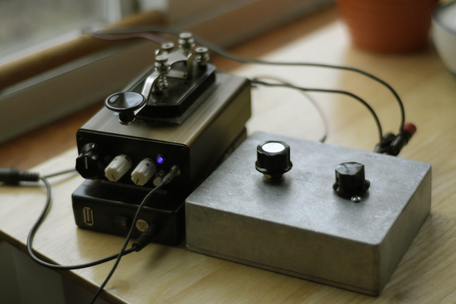
Portable 40m Direct-conversion Transceiver Design

Having finished my master’s degree over a year ago now, I’ve started to see my thesis show up on various academic web sites. I decided I should probably link it on this site in the event that anyone is interested in building and/or designing their own QRP mono-band radio. Additionally, I’ve been doing some more experiments with QRP setups and like using this rig as a qualification vehicle. Being a mono-bander with a very narrow receive bandwidth, I just find it more sensitive to picking up weak signals, and it’s very easy to listen to when operating in less noisy environments. I’ve done a lot of comparisons with the KX3 (thanks to KK7B), and sometimes it’s just easier to copy signals closer to the noise floor on the DCT.

With that being said, any later posts that utilize this transceiver will point back here for reference. A full text PDF of the design is listed here:

https://www.researchgate.net/publication/346429865_Design_of_a_7-MHz_Portable_Direct_Conversion_Transceiver_with_Digitally_Controlled_Keying

73s DE K2NXF

7MHz Transmitter with AVR Soft-keyer

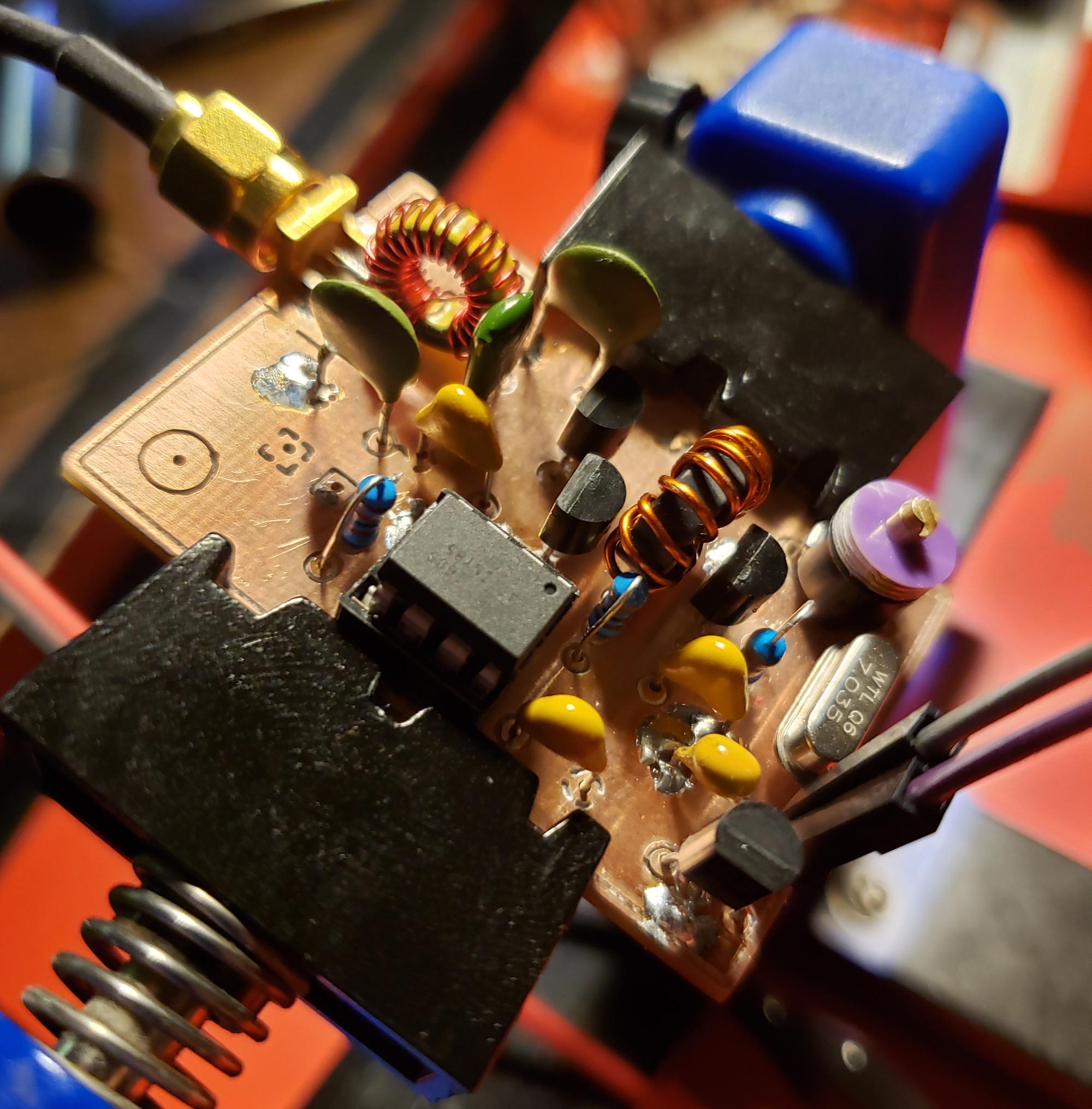
In my last post, I went over the design of a Colpitts crystal oscillator design that put out a moderately clean 7 MHz signal. In order to match the output impedance to 50 Ω, an NPN feedback pair (at least that’s what I’m calling it) was designed. While meeting the specs for driving an ADE-1 mixer, it consumed an unnecessary amount of current. I’ve been designing a tremolo effect recently (which I should be making on post on as well in the future) where I used a BS170 MOSFET to amplitude modulate an incoming audio signal. Without going into too much detail, I decided to adjust the DC bias point of an emitter-follower to sit at the threshold voltage of the BS170 to prevent from having to have a DC block immediately followed by another DC bias point. While looking at different transmitter designs on Homebrew RF Circuit Design Ideas, I came across a class C amplifier that used a similar technique to what I was doing in the tremolo effect combined with a Pierce oscillator. I did some experimentation and came up with the following circuit.

To be fair, this schematic is revision B, and it hasn’t been built yet. Revision A, however, is pretty much the same thing except R1 is omitted and the drain of Q3 connects to the source of Q6. The ATTiny85 takes the single-throw switch as the only input. When you turn it on, the switch acts like a standard on-off keyer for banging out morse code. If you hold the key down for 5 seconds, it changes to a beacon mode and starts tapping out my call sign. Holding the key down again changes operation into pulse mode with a frequency around 1 kHz. In pulse mode, you can actually pick up the signal on a standard AM receiver as seen in the demo video. The transmitter itself puts out 28 dBm running on a 12V supply and is around 82% efficient.

The PCB layout came out pretty quickly. It was the first time I have ever done double-sided PCB etching. Overall, I think it came out pretty well. There was small offset as you can see from the placement of the drill holes, but no harm, no foul. Performance was even a little better than the prototype. I mounted the board inside a Hammond 1590A enclosure and made a short demonstration video. It’s extremely simple, but I think it will be a useful piece of a larger project that I’m working on. It can also be easily adapted to a number of frequencies using a different crystal or loading Q2 to act as a frequency multiplier. I did experiment with this somewhat and was able to produce fairly strong second and third harmonics at the output. That’s about as far as I got though since I got distracted making theremin type sounds on my shortwave radio receiver.

#define cbi(sfr, bit) (_SFR_BYTE(sfr) &= ~_BV(bit))
#define sbi(sfr, bit) (_SFR_BYTE(sfr) |= _BV(bit))

#define CTL 0         // TX enable pin
#define SW  3        // input switch pin
#define N   10      // N periods in monopulse mode

bool            sw = LOW; 
bool            trig = LOW;               // monopulse trigger status
bool            tx = LOW;                // flag for TX enable
bool            keyer = LOW;            // flag for start of key press
int             mode = 0;              // modes: 0 => Key mode (default), 1 => ID mode, 2 => Monopulse
int             dit = 50;             // delay time for dit in ms
int             dash = 150;          // delay time for dash in ms
unsigned long   hold = 5e6;         // max hold value in microseconds
unsigned long   pause = 1e7;       // max pause between IDs in microseconds 
unsigned long   start = 0;        // start time in microseconds
unsigned long   last = 0;        // time of last ID;
long            c = 0;          // count variable for mode change


void setup() {
  pinMode(CTL,OUTPUT);
  pinMode(SW, INPUT);

  cli(); 
  /*--- TIMER1 CONFIG ---*/  
  TCCR1  = 0b01101000;
  GTCCR  = 0b00100000;
  
  TCCR0A = 0b00100000;
  TCCR0B = 0b00001011;    // last 3 bits set prescalar for Timer0

  cbi(TIFR,OCF1A);
  sbi(TIMSK,OCIE1A);
  OCR1A = 128;
  sei();

/* --- interrupt enable
    GIMSK = 0b00100000;     // turns on pin change interrupts
    PCMSK = 0b00001000;    // turn on interrupts on pins PB3
    sei(); 
*/
}

void loop() {  
  /*
    if (sw == LOW) { 
      start = micros();
      if (keyer == HIGH) {
       modeChk(); 
      } else {
       keyer = HIGH;
      }
    } else {
     keyer = LOW;
    }
  */
  // perform function based on mode
  switch(mode) {
    case 0:
      if (sw == LOW) {
        digitalWrite(CTL, HIGH); 
      } else {
        digitalWrite(CTL, LOW);
      }
    break;
    
    case 1:
      if (last == 0) {
        id();
      } else if ((micros() - last) > pause) {
        id();
      }
    break;
    
    case 2:
      if (sw == LOW) {
        pulse();
      }
    break;
  }

  trig = LOW;                 // monopulse trigger reset  
}

ISR(TIMER1_COMPA_vect) {
    sw = digitalRead(SW);
    if (sw == LOW) { 
      if (keyer == HIGH) {
       modeChk(); 
      } else {
       start = micros();
       keyer = HIGH;
       trig = HIGH;
      }
    } else {
     keyer = LOW;
    }
} 

void modeChk() {
  if ((micros() - start) > hold) {
     if (mode < 2) {
       mode++;
     } else {
       mode = 0;
     }
     start = micros();
     stat();
     delay(1000);
  }
}

void pulse() {
  // pulse TX on and off N times
  for(int n = 0; n < N; n++) {
      digitalWrite(CTL,HIGH);
      delayMicroseconds(500);
      digitalWrite(CTL,LOW);
      delayMicroseconds(500);
  }
}

void stat() {
  // tap out mode number in morse code
  for(int n = 0; n < mode; n++) {
      digitalWrite(CTL,HIGH);
      delay(dit);
      digitalWrite(CTL,LOW);
      delay(dit);
  }

    for(int n = 0; n < (5 - mode); n++) {
      digitalWrite(CTL,HIGH);
      delay(dash);
      digitalWrite(CTL,LOW);
      delay(dit);
  }
}

void id() {
  // tap out ID for K2NXF
  
// K
  digitalWrite(CTL,HIGH);
  delay(dash);
  digitalWrite(CTL,LOW);
  delay(dit);
  digitalWrite(CTL,HIGH);
  delay(dit);
  digitalWrite(CTL,LOW);
  delay(dit);
  digitalWrite(CTL,HIGH);
  delay(dash);

  digitalWrite(CTL,LOW);
  delay(dash);
  
// 2 
  digitalWrite(CTL,HIGH);
  delay(dit);
  digitalWrite(CTL,LOW);
  delay(dit);
  digitalWrite(CTL,HIGH);
  delay(dit);
  digitalWrite(CTL,LOW);
  delay(dit);
  digitalWrite(CTL,HIGH);
  delay(dash);
  digitalWrite(CTL,LOW);
  delay(dit);
  digitalWrite(CTL,HIGH);
  delay(dash);
  digitalWrite(CTL,LOW);
  delay(dit);
  digitalWrite(CTL,HIGH);
  delay(dash);
  digitalWrite(CTL,LOW);
  delay(dash);

// N
  digitalWrite(CTL,HIGH);
  delay(dash);
  digitalWrite(CTL,LOW);
  delay(dit);
  digitalWrite(CTL,HIGH);
  delay(dit);
  digitalWrite(CTL,LOW);
  delay(dash);

// X
  digitalWrite(CTL,HIGH);
  delay(dash);
  digitalWrite(CTL,LOW);
  delay(dit);
  digitalWrite(CTL,HIGH);
  delay(dit);
  digitalWrite(CTL,LOW);
  delay(dit);
  digitalWrite(CTL,HIGH);
  delay(dit);
  digitalWrite(CTL,LOW);
  delay(dit);
  digitalWrite(CTL,HIGH);
  delay(dash);
  digitalWrite(CTL,LOW);
  delay(dash);

// F
  digitalWrite(CTL,HIGH);
  delay(dit);
  digitalWrite(CTL,LOW);
  delay(dit);
  digitalWrite(CTL,HIGH);
  delay(dit);
  digitalWrite(CTL,LOW);
  delay(dit);
  digitalWrite(CTL,HIGH);
  delay(dash);
  digitalWrite(CTL,LOW);
  delay(dit);
  digitalWrite(CTL,HIGH);
  delay(dit);
  digitalWrite(CTL,LOW);
  delay(dash);

// new word
  digitalWrite(CTL,LOW);
  delay(dash);

last = micros();          // store current time at end of ID
  
} 

7MHz Crystal Oscillator Design

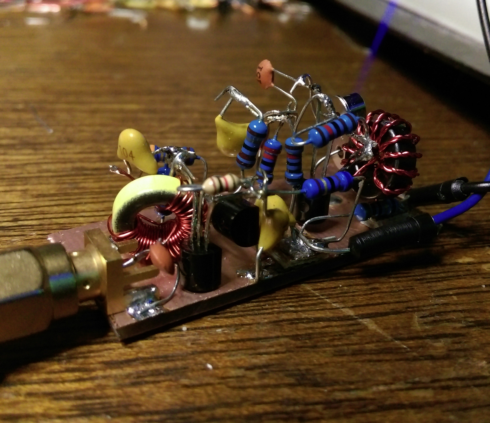
After constructing a 40m wire dipole that works with my SDR setup, I needed to start working on a transmission system. At the heart of virtually any RF system lies a stable oscillator, and crystal oscillators are ubiquitous in many low-power (QRP) rigs simply because they are so stable. After some rough math and a lot of simulations in LTSpice, I came up with this design to give me somewhere around 7 dBm of power.

The first stage is simple Colpitts oscillator topology with a “bent” 7.03 MHz crystal resonator. The 30 pF variable capacitor (C1) provides around 2 kHz of tuning. The output stage is a common-collector (Q4) and emitter-follower (Q3) with a negative feedback loop. I forget exactly where I saw this configuration, but I thought I would try it out and see if it worked. As you might have guessed, the output is loaded with higher order harmonics resulting in a waveform that doesn’t resemble a sine wave at all. I made sure to include a simple second-order low-pass Butterworth filter on the output to filter the output.

Pictured above is the ugly constructed version of the oscillator in all it’s dead-bug style. I built it on a scrap piece of double-sided FR4 and overall it’s performance came out fairly close to what LTSpice had predicted. I got around 6 dBm of output and the second harmonic is around 29 dB down (around -23 dBm). That’s not the cleanest of signals, but it’s about right for the filter. Below is the output shown on my HP 8595E spectrum analyzer.

For the next phase, I’ll likely be adding control of the oscillator via an ATTiny chip. This will give me the ability to automate on-off keying of the device turning it into a simple CW beacon. One thing that could be improved is the current draw (~40 mA) from the emitter-follower at Q3. Basically, it’s a class A amplifier so it’s not the most efficient design in the world, but it provides enough power for driving an ADE-1 and could run off a small solar panel if I wanted to use it in the field.

Testing a 40m Wire Dipole on Mt. Hood

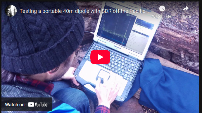
Here’s a quick video showing how I deployed a DIY 40m dipole antenna on Mt. Hood a while back. Though not the most interesting video, I think it shows the results pretty well. I used an AirSpy HF+ supplied by KK7B for a project I’m working on. A Panasonic Toughbook CF-30 helped stave off the rain.

The dipole itself is two sections of 65 ft speaker wire connected to an SO-239 connector. I took a couple of sections of PVC and drilled holes in the end so I could attach some paracord and hoist it into the air. I tuned the antenna using a fancy MFJ-259C antenna tuner. Bethany and I both had very cold fingers after pulling the antenna down.

I’ll be posting more on this as it develops… for real though.