LFO modulated simple VCF

lfo_vcf_rev_aa001

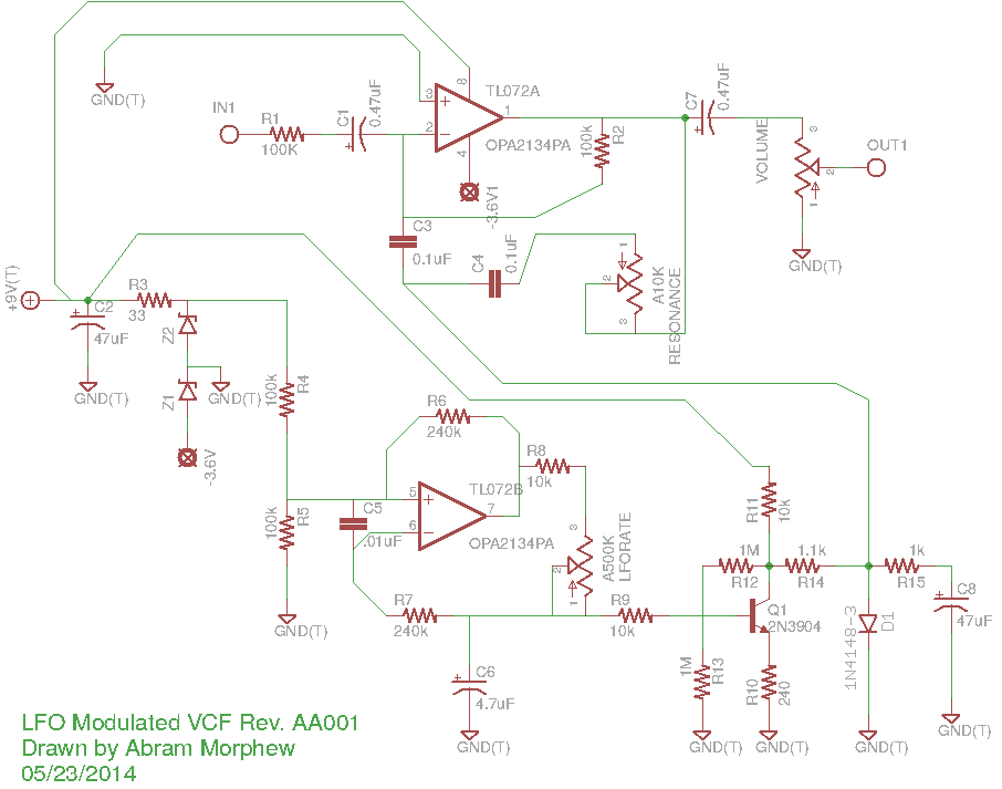
this is a rough draft of a circuit i’ve been working on based of the Simple VCF circuit floating out there. a big thanks to the original author for that. i’m sure there are some mistakes in here. it’s an odd one for sure, but it works on the breadboard. the opamp is a TL072. square-wave input from the generator comes out pretty sine-wave like which is what is desired. the output is a little noisy, but i will work that out with time.

solid-state tremolo for tube amps…

i’ve have a CBS-era Fender Bantam Bass in for repair that looks like a bowl of spaghetti inside the chassis. it’s a slew of yellow wire spread from one side to the other that resembles the web of a drunken spider. the amp has been modified to include a tremolo, reverb, and an effects loop that replaces the bass channel in the amp. the tremolo circuit was originally a Weber kit, but someone ripped a couple of the pads off the PCB while trying to modify the mod. i just redesigned a tremolo circuit based upon a simple dual opamp LFO using the Weber’s rectifier as a guide to get voltage from the heater filament supply. i attached the output to an “Intensity” pot and wired it into the cathode of the second half of the initial 12AX7. The schematic below has node “A” highlighted to show where the output of the tremolo circuit was connect in the amplifier.

bantam_layout_01

this is the layout as i was laying my new designed tremolo into the existing circuit.

bantam_layout_02

this is the part of the original Weber tremolo where the last tech (careful with that soldering iron, Eugene!) attempted to modulate of the negative grid bias. though a sound idea, the circuit itself wound up acting more like a compression effect by changing altering the bias when signal was present. also, a solid-state tremolo like this won’t have much of an overall effect on negative grid biasing due mostly to it’s weak output. rails on the LFO is roughly +5.5V resulting in a good 2.25Vpk (1.5Vrms) signal which is hardly enough to be noticeable. i also tend to avoid using trem circuits that re-bias the output stage simply because it does seem to put undue stress on the tubes and surrounding components. it seems more efficient and makes more sense to me to modulate signals while they’re still small.

bantam_layout_04

cleaner and a little more manageable.

bantam_layout_05

and with a fine custom-made panel, the old Bantam looks and sounds more like a ’65 Super Reverb than ever before. granted, not all steps were taken to black-face the amp, but a few value substitutions were made to achieve more of a black-face tone.

simple LFO circuits…

i was reading over this thread on diystompboxes.com about building an analog LFO circuit for some wild noise idea i’ve got brewing in the back of my head. i started messing around with some of the schematics on there and got a drifting saw wave out of it after a while. i was trying to take a picture of the wave itself on the oscilloscope which obviously didn’t turn out all that well. so many breadboards. yeesh.

TDA2040-based amp schematic with EQ…

well here’s the first draft of the simplest medium powered solid state design i could muster. TL082 can easily be substituted with a TL072 which is probably better anyhow (i just have all these TL082s laying around). the power supply i’m using more like 14-15V. both ICs should easily be able to handle up to 20V and that would allow for louder operation, but i think 15V is safe. all the resistors are 1/8W minus R20 which is 1/4W.

TDA2040 Instrument Amplifier

the need for small and portable amplifiers has arisen mainly by a desire to come up with some sort of all-purpose busking amplifier. here is the first screen shot of the output from the preamp section. the entire amplifier is powering an Eminence Beta-12LTA off of a mere 6V. don’t ask me how. it took a while to find the right combination of resistors for the TL082 to run stable at such a low voltage. it’s also surprisingly loud being that it’s about 26V away from the recommended supply (±16V). i’ll probably be posting a schematic soon.

SCHEMATIC: TL082 9V Active EQ…

an experimental EQ circuit based of the TL082 datasheet. i modified it to use a 9V battery, but could probably still use some work in terms of efficiency… as most things. nothing is ever finished really. the mid portion has a pretty high quiescence. fine tuning, of course, can be done with the resistor values and more dramatic differences by adjusting the cap values. if you happen to build it, shoot me an email and let me know what you changed or decided to change.

also keep in mind that the TL082 is a little noisy, so 6dB of highs will add in some noise. i kind of like it myself, but the TL072 is a better choice from what i understand.

SPICE: ngSpice plot test…

nothing too special here. i’ve been practicing my SPICE skills and attempting to work with a single-supply active EQ circuit based on the TL082. further research of this chip has pointed out that the TL072 is better for audio applications, but it seems that the differences are pretty minuscule.

here’s the spice code with the subcircuit that i downloaded off TI’s web site.

* Spice netlister for gnetlist
XU1 n7 	n2 	n1 	0 	n4 	TL082
C1	n4	n6				10U
C2	n5  n7				.1U
RL	n6	0				1MEG
R2 	n2 	n4 				10K
R1	n2 	0				10K
R3	n1	n7				10K
R4	n7  0				3.3K
V2 	n5	0 				SIN(0 1 1kHz)
V1 	n1 	0 				9
.TRAN 0.01ms 10ms
.PLOT n5 n6
.END


* TL082 OPERATIONAL AMPLIFIER "MACROMODEL" SUBCIRCUIT
* CREATED USING PARTS RELEASE 4.01 ON 06/16/89 AT 13:08
* (REV N/A)      SUPPLY VOLTAGE: +/-15V
* CONNECTIONS:   NON-INVERTING INPUT
*                | INVERTING INPUT
*                | | POSITIVE POWER SUPPLY
*                | | | NEGATIVE POWER SUPPLY
*                | | | | OUTPUT
*                | | | | |
.SUBCKT TL082    1 2 3 4 5
*
  C1   11 12 3.498E-12
  C2    6  7 15.00E-12
  DC    5 53 DX
  DE   54  5 DX
  DLP  90 91 DX
  DLN  92 90 DX
  DP    4  3 DX
  EGND 99  0 POLY(2) (3,0) (4,0) 0 .5 .5
  FB    7 99 POLY(5) VB VC VE VLP VLN 0 4.715E6 -5E6 5E6 5E6 -5E6
  GA    6  0 11 12 282.8E-6
  GCM   0  6 10 99 8.942E-9
  ISS   3 10 DC 195.0E-6
  HLIM 90  0 VLIM 1K
  J1   11  2 10 JX
  J2   12  1 10 JX
  R2    6  9 100.0E3
  RD1   4 11 3.536E3
  RD2   4 12 3.536E3
  RO1   8  5 150
  RO2   7 99 150
  RP    3  4 2.143E3
  RSS  10 99 1.026E6
  VB    9  0 DC 0
  VC    3 53 DC 2.200
  VE   54  4 DC 2.200
  VLIM  7  8 DC 0
  VLP  91  0 DC 25
  VLN   0 92 DC 25
.MODEL DX D(IS=800.0E-18)
.MODEL JX PJF(IS=15.00E-12 BETA=270.1E-6 VTO=-1)
.ENDS

Mellotronium revised…

here’s an update on the new additions/approach to the Mellotronium. i’m attempting to redo the SD card routines once i get the functionality added. using the SD library just doesn’t work right when reading byte values at 8kHz. i’ve looked into the WaveHC library with the most success, but had to modify not to use an external DAC. a new wav file playing solution from the SD card will have to be found.

without the clunky SD lib, program space has opened up… a lot of it in fact. now i’ve started using a wavetable. this video just has a single sine wave, but it’s modulate with the LFO and its seven different waveforms not to mention an amplitude modulating ADSR filter.

the breadboard to the side contains an experimental active 2-band EQ (TLO82-based) which needs some work. if anyone has any experience with this, i would love to know why the schematic in the datasheet doesn’t work at all. i wound up having to recall the usage from a different schematic where you make a voltage divider from and peer it into the positive terminal on both opamps. it works… in a way. i think i’ve inverted the wave form or something strange. it also sometimes works better as a radio than an EQ which i think i like. it made for some interesting heterodyning.