-

This AI kills Fascists: Musing on AI, art, and music
So, AI is a commonly thrown around term now, and, like most things, it’s something that people have very strong opinions about, and most of them are within good reason. I have been recently pulling models from Huggingface and working on training my own models to get a better sense of, first off, what AI…
-
Nokto Kiel Ĉi Tiu
Ĉi tiu filmeto estis kreita kiel memoraĵo por amiko kiu perdis sian amikon.
-
Who was Floyd Fitz? Enigma of the Caddo River
This short film is a back log of video footage that I’ve been releasing the older footage on The 8088 Record Collective YouTube channel. Looking in the used cassette tape bins at small-town thrift stores can expose a hidden world of lost voices and ghostly apparitions. This documentary explores the tragic life of an enigmatic…
-
“Ĉu Iu Estas Tie?” (Short film in Esperanto)
Bethany and I made a short film for the American Good Film Festival back in March. It’s an anecdote centering around a child’s toy endowed with artificial intelligence that wakes up alone in a forgotten forest. Bethany kaj mi faris mallongan filmeton por la Usona Bona Esperanto Film-festivalo antaŭ en marto. Ĝi estas rakonto ĉirkaŭ…
-
Linux Audio Production: Getting started with Jack and MIDI
Last year, I posted this quick tutorial on the SMBA YouTube channel walking through the steps to use a MIDI controller with Jack using Xubuntu 20.04. I am posting it hear just for the sake of consistency and good housekeeping. Hopefully, I’ll get to make some more of these soon.
-
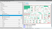
Running Autodesk EAGLE 9.6.2 on Xubuntu 22.04
So, I did a fresh install of Xubuntu 22.04 on a Dell Latitude 7390 with an Intel UHD 620 display adapter. I had some issues with the machine locking up just a few minutes after startup. I was able to resolve this by adding the following kernel option to the /etc/default/grub file. The resolved that…
-
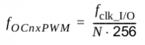
Arduino: Audio Frequency Generator
Back in good ol’ 2012 (the year the world was supposed to end), I posted some code for a simple Arduino controlled low-frequency oscillator (LFO). It has made its way into some very interesting projects over the years, but recently I was asked in the comments if the code could be modified to have a…
-
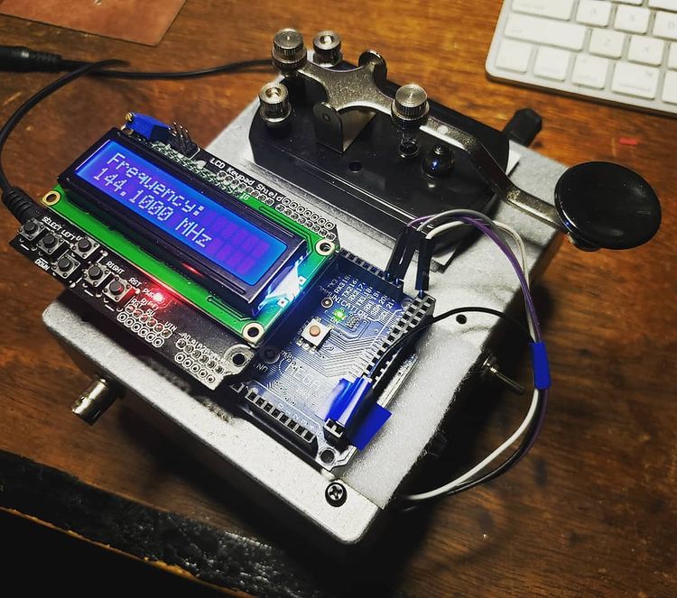
Arduino: 1-Watt 2m Transmitter with RF Signal Generator
Since I do a lot of RF projects, I wanted to see if I could make a 2m power amplifier using a minimal set of components. I have a number of BS170 MOSFET transistors that I’ve used for dozens of applications over the years from guitar pedal pre-amps to digital control circuits. I started this…
-
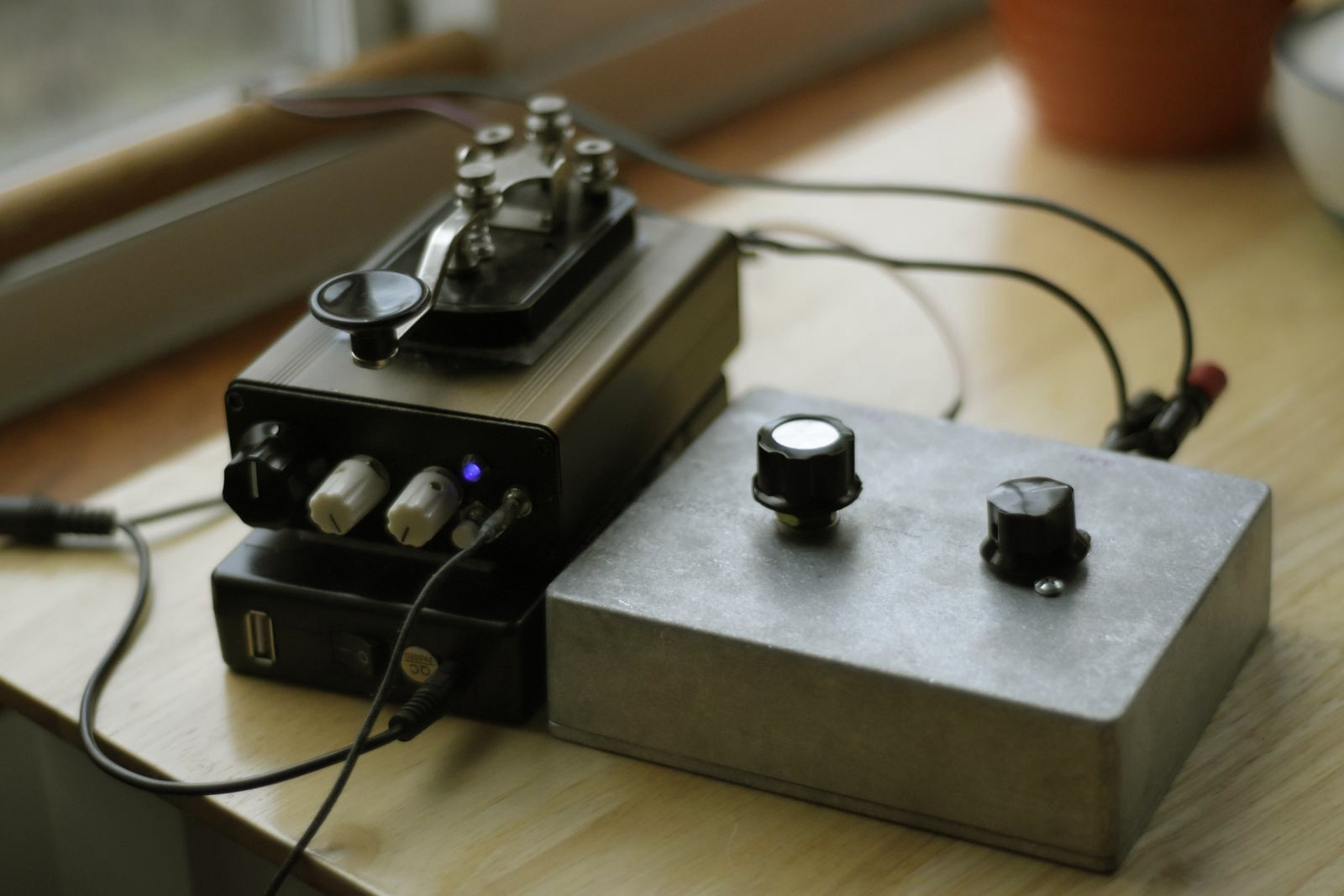
Portable 40m Direct-conversion Transceiver Design
Having finished my master’s degree over a year ago now, I’ve started to see my thesis show up on various academic web sites. I decided I should probably link it on this site in the event that anyone is interested in building and/or designing their own QRP mono-band radio. Additionally, I’ve been doing some more…