Arduino: 1-Watt 2m Transmitter with RF Signal Generator

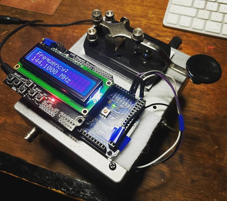
Since I do a lot of RF projects, I wanted to see if I could make a 2m power amplifier using a minimal set of components. I have a number of BS170 MOSFET transistors that I’ve used for dozens of applications over the years from guitar pedal pre-amps to digital control circuits. I started this project by building a class A amplifier on a bare piece of copper laminate. I was able to get 9 dB of gain with a power output of 15 dBm and a quiescent current of 83 mA. The schematic is shown below. R3 and R4 can be omitted if you happen to be building the circuit and replaced with 50 ohm SMA connectors. I used a variable cap at C3 to tune the circuit for maximum output power,

With 15 dBm of output power, I thought this would be adequate to drive a power amplifier stage. I nabbed some 2SC1970 transistors off eBay for a few bucks and started experimenting with the application circuit in the datasheet. This transistor is quite old by modern standards, but they were cheap and in a TO-220 package, so I figured they could take a beating. The standard application circuit was a good jumping off point for starting the design, and I was able to easily make changes to the air-core inductors by compressing and stretching the windings. I wound up just getting as close as I could with the inductors and relying on the variable capacitors in the circuit to get as much power as I could.

The LO portion of the transmitter was an Si5351 clock signal generator controlled by an ATMega2560 Arduino board. It’s able to get up to 160 MHz (200 MHz now in the Si5351B chips) and is programmed via an I2C port. I setup button 5 (Select) on the LCD shield to enable the LO later on, but I just had it running originally at startup and then connected the straight key in series with the 12V supply (widow-maker style) to the PA.

Above is the measured output on the old Tektronix TDS 360 oscilloscope. Measured power output is right at 1 watt. The second harmonic is a little higher than I would have liked, but an added LPF to the output should help fix that right up. The last thing to do was to get out in the rain in January and see if someone could pick it up. I hooked up a 3-element yagi to the output and the signal from the transmitter was picked up by W7YOZ in Shelton, WA some 22 miles to the north east.

Of course, here is the Arduino code for the RF signal generator using the Adafruit Si5351 clock generator board. The controls need to be incorporated into an interrupt trigger to make the thing more controllable, but it hasn’t been so annoying that I’ve needed to fix it as of yet. Just fair warning in case someone out there in the world decides to use it for anything.

// Arduino RF Signal Generator
// author: Abram Morphew
// date: 2019.04.25

#include <Wire.h>
#include <Adafruit_SI5351.h>
#include <LiquidCrystal.h>

Adafruit_SI5351 clockgen = Adafruit_SI5351();
LiquidCrystal lcd(8, 9, 4, 5, 6, 7);

long frequency = 144100000;
long inc = 1000;
char* data = "0";
int btn = 0;
bool keyPress = false;
bool enable = false;

void setup() {
  lcd.begin(16,2);
  lcd.print("Initialize");
  delay(500);
  
  /* Initialise the sensor */
  if (clockgen.begin() != ERROR_NONE) {
    lcd.print("Ooops, no Si5351 detected ... Check your wiring or I2C ADDR!");
    while(1);
  }

  setfrequency(frequency);
  delay(100);
  lcd.clear();
  
}

void loop() {
  if (keyPress == true) {
    setfrequency(frequency);
    keyPress = false;
  }
  
  // set title:
  lcd.setCursor(0,0);
  lcd.print("Frequency: ");

  // update frequency 
  lcd.setCursor(0, 1);
  lcd.print(frequency/1e6,3);
  lcd.print(" MHz ");

  btn = readkeypad();
  if ((btn == 1) &amp;&amp; (frequency + inc &lt;= 155e6)) { frequency = frequency + inc; keyPress = true; delay(100); }
  if ((btn == 2) &amp;&amp; (frequency - inc &gt;= 420e3)) { frequency = frequency - inc; keyPress = true; delay(100); }

  if ((btn == 3) &amp;&amp; (inc &lt; 1e8)) { inc = inc * 10; delay(100); }
  if ((btn == 4) &amp;&amp; (inc &gt; 1e4)) { inc = inc / 10; delay(100); } 
  if (btn == 5) {
    clockgen.enableOutputs(true);
  }  
  
  if (btn != 5) {
    clockgen.enableOutputs(false);
  }
  
  delay(10);
}

int readkeypad(){
      int adc_key_in = analogRead(0); //
      int ret = 0;

      if (adc_key_in &lt; 50) ret = 4;
      if ( (adc_key_in &gt; 800) &amp;&amp; (adc_key_in &lt; 1150)) ret = 0;
      if ( (adc_key_in &gt;  80) &amp;&amp; (adc_key_in &lt; 150) ) ret = 1;
      if ( (adc_key_in &gt; 250) &amp;&amp; (adc_key_in &lt; 350) ) ret = 2;
      if ( (adc_key_in &gt; 400) &amp;&amp; (adc_key_in &lt; 500) ) ret = 3;
      if ( (adc_key_in &gt; 500) &amp;&amp; (adc_key_in &lt; 800) ) ret = 5;
  
      
      //lcd.print(adc_key_in);
      return ret;
 }

int setfrequency(long frequency) {
  int m = 0;
  int n = 0;
  int fs = 8;
  clockgen.enableOutputs(false);

  if (frequency &gt; 55e6) {
    fs = 8;
  } else if ((frequency &lt;= 55e6) &amp;&amp; (frequency &gt; 25e6)) {
    fs = 16;
  } else if ((frequency &lt;= 25e6) &amp;&amp; (frequency &gt; 10e6)) {
    fs = 32;
  } else if ((frequency &lt;= 10e6) &amp;&amp; (frequency &gt; 6e6)) {
    fs = 64;
  } else if ((frequency &lt;= 6e6) &amp;&amp; (frequency &gt; 3e6)) {
    fs = 128;
  } else if ((frequency &lt;= 6e6) &amp;&amp; (frequency &gt; 2.1e6)) {
    fs = 256;
  } else if ((frequency &lt;= 2.1e6) &amp;&amp; (frequency &gt; 1e6)) {
    fs = 512;
  } else if (frequency &lt;= 1e6) {
    fs = 900;
  }

  // determine m, n, and d from frequency value
  m = floor(frequency*fs/25e6);
  n = ((frequency*fs/25e6) - m)*1000;
  clockgen.setupPLL(SI5351_PLL_A, m, n, 1000);
  clockgen.setupMultisynth(0, SI5351_PLL_A, fs, 0, 1);
}

7MHz Transmitter with AVR Soft-keyer

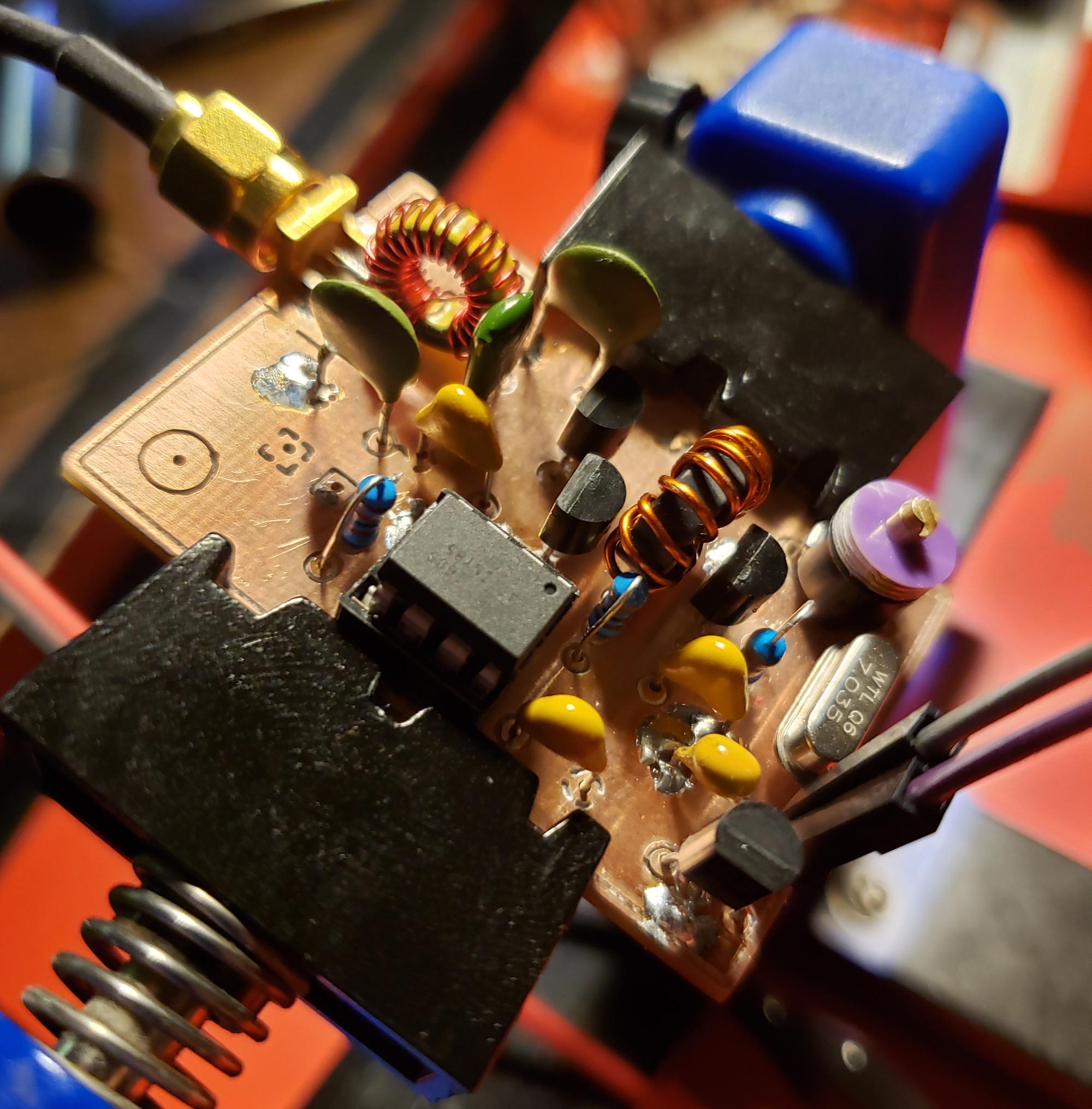
In my last post, I went over the design of a Colpitts crystal oscillator design that put out a moderately clean 7 MHz signal. In order to match the output impedance to 50 Ω, an NPN feedback pair (at least that’s what I’m calling it) was designed. While meeting the specs for driving an ADE-1 mixer, it consumed an unnecessary amount of current. I’ve been designing a tremolo effect recently (which I should be making on post on as well in the future) where I used a BS170 MOSFET to amplitude modulate an incoming audio signal. Without going into too much detail, I decided to adjust the DC bias point of an emitter-follower to sit at the threshold voltage of the BS170 to prevent from having to have a DC block immediately followed by another DC bias point. While looking at different transmitter designs on Homebrew RF Circuit Design Ideas, I came across a class C amplifier that used a similar technique to what I was doing in the tremolo effect combined with a Pierce oscillator. I did some experimentation and came up with the following circuit.

To be fair, this schematic is revision B, and it hasn’t been built yet. Revision A, however, is pretty much the same thing except R1 is omitted and the drain of Q3 connects to the source of Q6. The ATTiny85 takes the single-throw switch as the only input. When you turn it on, the switch acts like a standard on-off keyer for banging out morse code. If you hold the key down for 5 seconds, it changes to a beacon mode and starts tapping out my call sign. Holding the key down again changes operation into pulse mode with a frequency around 1 kHz. In pulse mode, you can actually pick up the signal on a standard AM receiver as seen in the demo video. The transmitter itself puts out 28 dBm running on a 12V supply and is around 82% efficient.

The PCB layout came out pretty quickly. It was the first time I have ever done double-sided PCB etching. Overall, I think it came out pretty well. There was small offset as you can see from the placement of the drill holes, but no harm, no foul. Performance was even a little better than the prototype. I mounted the board inside a Hammond 1590A enclosure and made a short demonstration video. It’s extremely simple, but I think it will be a useful piece of a larger project that I’m working on. It can also be easily adapted to a number of frequencies using a different crystal or loading Q2 to act as a frequency multiplier. I did experiment with this somewhat and was able to produce fairly strong second and third harmonics at the output. That’s about as far as I got though since I got distracted making theremin type sounds on my shortwave radio receiver.

#define cbi(sfr, bit) (_SFR_BYTE(sfr) &amp;= ~_BV(bit))
#define sbi(sfr, bit) (_SFR_BYTE(sfr) |= _BV(bit))

#define CTL 0         // TX enable pin
#define SW  3        // input switch pin
#define N   10      // N periods in monopulse mode

bool            sw = LOW; 
bool            trig = LOW;               // monopulse trigger status
bool            tx = LOW;                // flag for TX enable
bool            keyer = LOW;            // flag for start of key press
int             mode = 0;              // modes: 0 =&gt; Key mode (default), 1 =&gt; ID mode, 2 =&gt; Monopulse
int             dit = 50;             // delay time for dit in ms
int             dash = 150;          // delay time for dash in ms
unsigned long   hold = 5e6;         // max hold value in microseconds
unsigned long   pause = 1e7;       // max pause between IDs in microseconds 
unsigned long   start = 0;        // start time in microseconds
unsigned long   last = 0;        // time of last ID;
long            c = 0;          // count variable for mode change


void setup() {
  pinMode(CTL,OUTPUT);
  pinMode(SW, INPUT);

  cli(); 
  /*--- TIMER1 CONFIG ---*/  
  TCCR1  = 0b01101000;
  GTCCR  = 0b00100000;
  
  TCCR0A = 0b00100000;
  TCCR0B = 0b00001011;    // last 3 bits set prescalar for Timer0

  cbi(TIFR,OCF1A);
  sbi(TIMSK,OCIE1A);
  OCR1A = 128;
  sei();

/* --- interrupt enable
    GIMSK = 0b00100000;     // turns on pin change interrupts
    PCMSK = 0b00001000;    // turn on interrupts on pins PB3
    sei(); 
*/
}

void loop() {  
  /*
    if (sw == LOW) { 
      start = micros();
      if (keyer == HIGH) {
       modeChk(); 
      } else {
       keyer = HIGH;
      }
    } else {
     keyer = LOW;
    }
  */
  // perform function based on mode
  switch(mode) {
    case 0:
      if (sw == LOW) {
        digitalWrite(CTL, HIGH); 
      } else {
        digitalWrite(CTL, LOW);
      }
    break;
    
    case 1:
      if (last == 0) {
        id();
      } else if ((micros() - last) &gt; pause) {
        id();
      }
    break;
    
    case 2:
      if (sw == LOW) {
        pulse();
      }
    break;
  }

  trig = LOW;                 // monopulse trigger reset  
}

ISR(TIMER1_COMPA_vect) {
    sw = digitalRead(SW);
    if (sw == LOW) { 
      if (keyer == HIGH) {
       modeChk(); 
      } else {
       start = micros();
       keyer = HIGH;
       trig = HIGH;
      }
    } else {
     keyer = LOW;
    }
} 

void modeChk() {
  if ((micros() - start) &gt; hold) {
     if (mode &lt; 2) {
       mode++;
     } else {
       mode = 0;
     }
     start = micros();
     stat();
     delay(1000);
  }
}

void pulse() {
  // pulse TX on and off N times
  for(int n = 0; n &lt; N; n++) {
      digitalWrite(CTL,HIGH);
      delayMicroseconds(500);
      digitalWrite(CTL,LOW);
      delayMicroseconds(500);
  }
}

void stat() {
  // tap out mode number in morse code
  for(int n = 0; n &lt; mode; n++) {
      digitalWrite(CTL,HIGH);
      delay(dit);
      digitalWrite(CTL,LOW);
      delay(dit);
  }

    for(int n = 0; n &lt; (5 - mode); n++) {
      digitalWrite(CTL,HIGH);
      delay(dash);
      digitalWrite(CTL,LOW);
      delay(dit);
  }
}

void id() {
  // tap out ID for K2NXF
  
// K
  digitalWrite(CTL,HIGH);
  delay(dash);
  digitalWrite(CTL,LOW);
  delay(dit);
  digitalWrite(CTL,HIGH);
  delay(dit);
  digitalWrite(CTL,LOW);
  delay(dit);
  digitalWrite(CTL,HIGH);
  delay(dash);

  digitalWrite(CTL,LOW);
  delay(dash);
  
// 2 
  digitalWrite(CTL,HIGH);
  delay(dit);
  digitalWrite(CTL,LOW);
  delay(dit);
  digitalWrite(CTL,HIGH);
  delay(dit);
  digitalWrite(CTL,LOW);
  delay(dit);
  digitalWrite(CTL,HIGH);
  delay(dash);
  digitalWrite(CTL,LOW);
  delay(dit);
  digitalWrite(CTL,HIGH);
  delay(dash);
  digitalWrite(CTL,LOW);
  delay(dit);
  digitalWrite(CTL,HIGH);
  delay(dash);
  digitalWrite(CTL,LOW);
  delay(dash);

// N
  digitalWrite(CTL,HIGH);
  delay(dash);
  digitalWrite(CTL,LOW);
  delay(dit);
  digitalWrite(CTL,HIGH);
  delay(dit);
  digitalWrite(CTL,LOW);
  delay(dash);

// X
  digitalWrite(CTL,HIGH);
  delay(dash);
  digitalWrite(CTL,LOW);
  delay(dit);
  digitalWrite(CTL,HIGH);
  delay(dit);
  digitalWrite(CTL,LOW);
  delay(dit);
  digitalWrite(CTL,HIGH);
  delay(dit);
  digitalWrite(CTL,LOW);
  delay(dit);
  digitalWrite(CTL,HIGH);
  delay(dash);
  digitalWrite(CTL,LOW);
  delay(dash);

// F
  digitalWrite(CTL,HIGH);
  delay(dit);
  digitalWrite(CTL,LOW);
  delay(dit);
  digitalWrite(CTL,HIGH);
  delay(dit);
  digitalWrite(CTL,LOW);
  delay(dit);
  digitalWrite(CTL,HIGH);
  delay(dash);
  digitalWrite(CTL,LOW);
  delay(dit);
  digitalWrite(CTL,HIGH);
  delay(dit);
  digitalWrite(CTL,LOW);
  delay(dash);

// new word
  digitalWrite(CTL,LOW);
  delay(dash);

last = micros();          // store current time at end of ID
  
} 

Basic Voltage-Controlled Amplifier

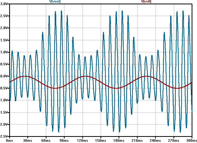
I’ve been looking at the theoretical principles that govern the voltage-controlled amplifier (VCA) recently and came across some simple VCA designs that caught my attention. A common technique involves a JFET and an opamp to achieve VCA type operation by using the JFET as a voltage-controlled resistor somewhere in the input path. I’ve seen a good deal of these circuits out there, but I had trouble getting good simulation results from what I had seen. I cam across an article by Rod Elliot of Elliot Sound Products which covered some nice history and interesting discussion of the VCA in general. After going over the information there, I came up with this design based on some of the more basic designs presented.

Basic VCA LTSpice Schematic

One of the things I’ve been most interested in is trying to accomplish this with a single supply which is common in most stompbox setups. In the schematic, there’s an emitter-follower stage just to act as a buffer for the input signal followed by an inverting opamp stage. To make this work, both C1 and C2 are required to effectively AC couple both input signals (Vin and Vctl) to the opamp stage. There’s an RC network that is supposed to tame the distortion in the output by taking a portion of the output and connecting it to the input of the J201. The article explains this in decent detail. In simulation, the it seems to smooth out the non-linearity of the JFET as Vctl changes. Using the J201, LTSpice gives a decent linear-like response over a range of around 500 mV (0 to -500 mV at the input) and operates decently with a 500 mVp signal.

VCA Linearity Test

For use with an LFO, I found that the best results happen with a slight negative voltage offset and a signal who’s amplitude peaks at 0V (i.e. 250 mV sinusoidal signal with a -250 mV offset). Of course, this is all highly dependent on the threshold voltage of the J201 which can range from -0.3 V to -1.5 V according to the Fairchild datasheet. It will be interesting to see the results of this circuit on a breadboard.

LFO modulated VCA Simulation

References:
[1] Gray, P. (2009). Analysis and design of analog integrated circuits. New York: Wiley.

[2] Sound.whsites.net. (2017). VCAs. [online] Available at: http://sound.whsites.net/articles/vca-techniques.html [Accessed 1 Sep. 2017].

The Cicada: a push-pull vacuum tube amplifier build

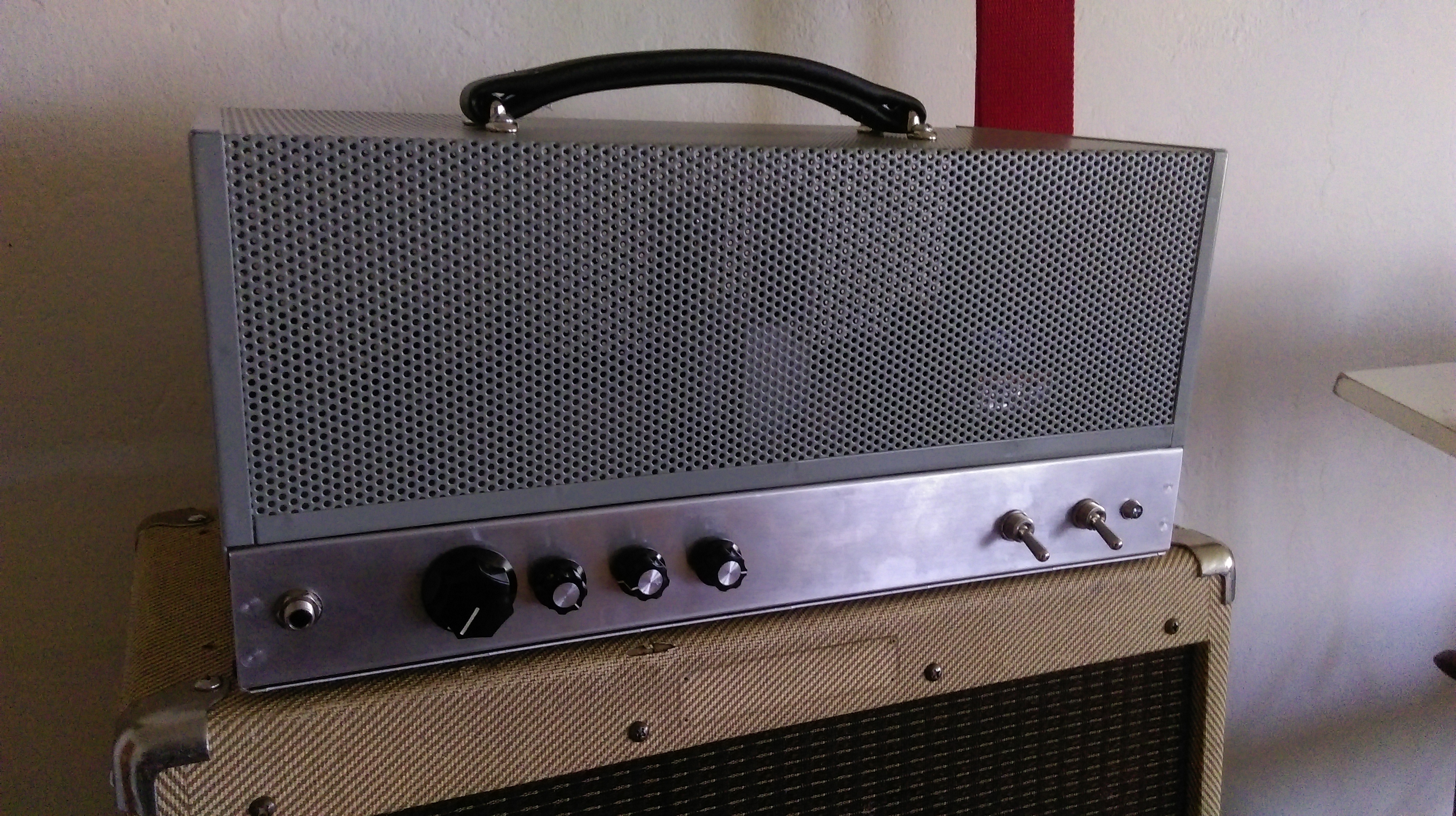
Well, 2017 is more than half over now. This means I should probably post something to get at least one post in for this year. I’ve been meaning to do a write up about this project for a while, but time isn’t as freely available as I would like it to be. Go figure. I had been wanting to try a push-pull tube amp build for years and scrapped together a design from parts I had lying around. I play a Gretsch G5265 baritone guitar with bass VI strings (this was its original configuration when I got it back in ’08), and I’ve had a hard time finding an amp that really suits the sound of the mini-humbuckers and it’s very deep tone. I decided to etch together a blackface Bassman-like amp with a tone stack capable of giving it the upper-mid range that it needs to bring out the high notes of the instrument. Unfortunately, I still haven’t gone through a rigorous analysis of the design other than some tone stack simulations in LTspice, but I’ll give out the schematic and details of the build.

6L6GC amp schematic

First off, the secondary voltage of the transformer should read around 300 V peak or around 600V peak-to-peak. Unlike a typical Bassman, it lacks a choke and the negative feedback resistor value is pretty large by comparison. I just swapped out values until I liked the sound and the oscillations stopped happening. I might swap this out with a 22k resistor again, but I can’t complain so far about the tone. There is one side of a 12AU7 (V2b) which is currently unused. I might make a simple phase shift oscillator of that later to make a tremolo circuit. If someone wanted to swap out 12AX7s in this design, the thing would be hella dirty and loud for a 40-ish watt amplifier (I still have to measure the actual wattage delivered to the load).

6L6GC amp tone simulation

Here is a plot of the magnitude of the tone stack simulation with the treble at noon, the bass at 9 o’clock, and the mid all the way up. The behavior of the stack is interesting as changing any one of the pots can have a sometimes dramatic effect on the position of the mid center frequency. This is one of the made drawbacks of passive tone stacks since the change in resistance of any potentiometer changes the transfer function for the network. However, the tone stack does lend itself to also listening to recorded music when setup properly. We’ve actually used this as a PA head in conjunction with a subwoofer which worked out really well. It’s bright nature actually seems to work well for vocals and low-mid while the sub picks up anything under 150 Hz or so.

6L6GC amp guts

I have a number of pictures that show how the layout progressed from right to left inside the chassis. Basically, I just started on the right side closest to the power transformer and worked towards the input. The biasing circuitry is towards the front of the amp by the large filter caps in the picture.

6L6GC tube glow

I was reading through Theory and Application of Electron Tubes [1] and discovered that the blue plasma color is actually caused by a spray of electrons from the cathode that actually overshoot the anode and slam into the glass. In the picture, you can see how the blue light only cover the area surrounding the big gray metal anode inside the glass. My new JJs that I put in there don’t have such an extreme blue color to them during operation.

Lastly, pictured above is the final build with the steel cage situated on top. The chassis is aluminum while the cage is steel. Both are manufactured by the fine folks at Hammond. I picked these up off CE Distribution’s website for a decent price. There’s definitely some room for improvement in the overall, but I really didn’t think it would work at all. I do think that it’s one of the nicest sounding amps I’ve ever owned regardless of the fact that I built it. I’ll post some sound samples eventually with some different instruments so anyone who stumbles upon this post can hear what the amp sounds like at lower volumes at least.

References
[1] Reich, H. (1944). Theory and Application of Electron Tubes. New York [usw.]: Mc Graw-Hill.

Class AB amplifier test

image

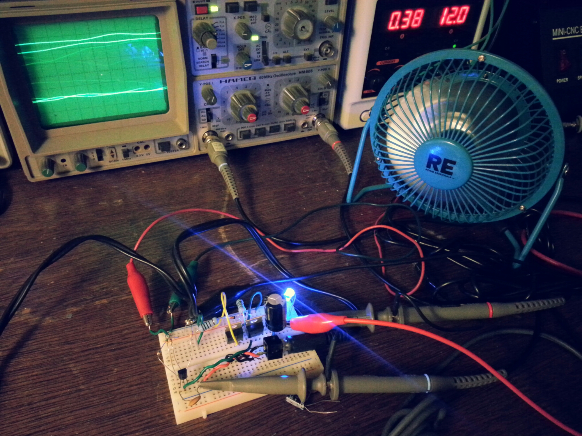
this was an attempt at designing a simple transformer-less class AB amplifier using two BJT power transistors. i setup the USB fan to protect against thermal runaway and cool off the transistors during operation. it took me looking over several schematics to realize that the the emitters of both the PNP and NPN transistors were tied together. the collector of the PNP (TIP32C) is grounded which is obvious! the synapses just weren’t seeing the PNP symbol as upside down. it’s definitely something i’ll have to work on. i’d like at some point to have a nice 40W amp based on a similar configuration.

solid-state tremolo for tube amps…

i’ve have a CBS-era Fender Bantam Bass in for repair that looks like a bowl of spaghetti inside the chassis. it’s a slew of yellow wire spread from one side to the other that resembles the web of a drunken spider. the amp has been modified to include a tremolo, reverb, and an effects loop that replaces the bass channel in the amp. the tremolo circuit was originally a Weber kit, but someone ripped a couple of the pads off the PCB while trying to modify the mod. i just redesigned a tremolo circuit based upon a simple dual opamp LFO using the Weber’s rectifier as a guide to get voltage from the heater filament supply. i attached the output to an “Intensity” pot and wired it into the cathode of the second half of the initial 12AX7. The schematic below has node “A” highlighted to show where the output of the tremolo circuit was connect in the amplifier.

bantam_layout_01

this is the layout as i was laying my new designed tremolo into the existing circuit.

bantam_layout_02

this is the part of the original Weber tremolo where the last tech (careful with that soldering iron, Eugene!) attempted to modulate of the negative grid bias. though a sound idea, the circuit itself wound up acting more like a compression effect by changing altering the bias when signal was present. also, a solid-state tremolo like this won’t have much of an overall effect on negative grid biasing due mostly to it’s weak output. rails on the LFO is roughly +5.5V resulting in a good 2.25Vpk (1.5Vrms) signal which is hardly enough to be noticeable. i also tend to avoid using trem circuits that re-bias the output stage simply because it does seem to put undue stress on the tubes and surrounding components. it seems more efficient and makes more sense to me to modulate signals while they’re still small.

bantam_layout_04

cleaner and a little more manageable.

bantam_layout_05

and with a fine custom-made panel, the old Bantam looks and sounds more like a ’65 Super Reverb than ever before. granted, not all steps were taken to black-face the amp, but a few value substitutions were made to achieve more of a black-face tone.

no. 5 re-appropriation…

no5_redesign

this is a re-appropriation of a Fender Frontman 15-B. it’s one 8″ speaker in a closed cabinet primarily designed as a really cheap bass amp to be included in starter packs. having gutted the amp a few years ago and replaced it with the contents from the No. 5 tube amp project, i got some time to rework the circuit into something more usable.

the additions include a tone stack, second gain stage, and a stand-by switch. the power amp is now wired as a pentode instead of a triode, and i didn’t feel it necessary to have a switch between the two modes. it still needs a little work to keep it from self-oscillating at high volumes. thanks to those guys who run AX84.com for their P1 project. it definitely helped the way i thought about redesigning the amp.

TDA2040-based amp schematic with EQ…

well here’s the first draft of the simplest medium powered solid state design i could muster. TL082 can easily be substituted with a TL072 which is probably better anyhow (i just have all these TL082s laying around). the power supply i’m using more like 14-15V. both ICs should easily be able to handle up to 20V and that would allow for louder operation, but i think 15V is safe. all the resistors are 1/8W minus R20 which is 1/4W.

LM386-based “Esteli” demo by Alex Wilson

an older video, but one i’ve been wanting to post for some time. this is Alex Wilson of Son Cats playing on one of the several cigar-box amps i’ve constructed. this one, in particular, had one of the best sounds during the more work-with-what-is-available days. i thought the video was a great demo of an application best suited for a small 1/2 watt amp. thanks, Alex.