200 kHz Arduino Clock Generator

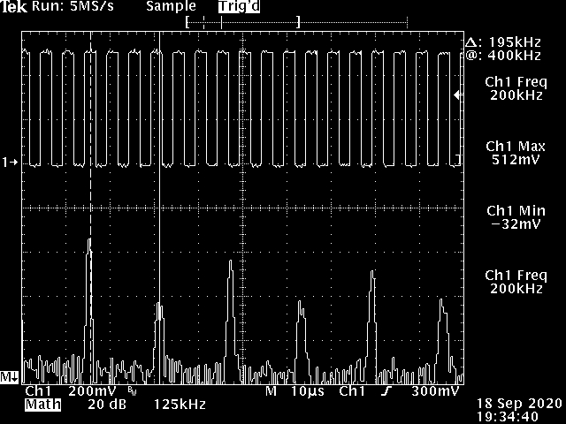
Someone contacted me recently about using an ATMega328 to generate a 200 kHz clock signal for a BBD analog delay chip. I finally had a few minutes today to sit down and ensure that this code works. Varying the OCR0A value acts as a frequency adjustment on the output following the formula: f = 16e6 / (4 * OCR0A) where OCR0A != 0. With a value of 0, the output frequency is roughly 8 MHz. It seemed fairly stable enough at this frequency, but I imagine that it would start having issues with more instructions. Either way, it makes for a very usable clock signal in the kHz range. I’ll try it out on a BBD hopefully one day myself and see.

// ===== 200 kHz Clock Signal Generator ==== //
int  pin = 6;
byte data = LOW;

void setup() {
  setupTimer();
  pinMode(pin, OUTPUT);
                 // f = 16e6 / (4 * OCR0A)
  OCR0A = 20;    // varies CLK frequency: 0 => 8 MHz, 255 => 16 kHz
  digitalWrite(pin,data);
}

void loop() {

}

void setupTimer() {
  cli(); 
 /*--- TIMER0 CONFIG ---*/  
  TCCR0A = 0b11000001;
  TCCR0B = 0b00001001;    // last 3 bits set prescalar for Timer0
  TIMSK0 = 0b00000010;    // set OCIE0A high
  TIFR0  = 0b00000010;    // set OCF0A high
  sei(); 
}

ISR(TIMER0_COMPA_vect) {
  data = !data;
  digitalWrite(pin, data);
}
</pre>

sqrt() reverb…

sqrt_reverb4

this was the final build before it shipped out. circuit is a simple MOSFET (BS170) driver stage followed by two JFET (J201) recovery stages. i’ve included a sound sample of a similar reverb i built later without the second recovery stage and clipping diodes. it makes for a much more subtle reverb, but also tames the noise floor from the Belton module.

[audio:http://abrammorphew.com/notes/wp-content/uploads/2013/02/sqrt_reverb_demo_02.mp3|titles=sqrt() reverb demo #01]

this is the actual first build. the “dirty verb” comes in towards the end which just switching on a pair of germanium clipping diodes. you get more reverb for your buck with the second JFET stage, but i haven’t found a way to cool down the noise just yet. that’ll be revision 5… maybe 7. [audio:http://abrammorphew.com/notes/wp-content/uploads/2013/02/reverb-test02.mp3|titles=sqrt reverb demo #02]

Mellotronium revised…

here’s an update on the new additions/approach to the Mellotronium. i’m attempting to redo the SD card routines once i get the functionality added. using the SD library just doesn’t work right when reading byte values at 8kHz. i’ve looked into the WaveHC library with the most success, but had to modify not to use an external DAC. a new wav file playing solution from the SD card will have to be found.

without the clunky SD lib, program space has opened up… a lot of it in fact. now i’ve started using a wavetable. this video just has a single sine wave, but it’s modulate with the LFO and its seven different waveforms not to mention an amplitude modulating ADSR filter.

the breadboard to the side contains an experimental active 2-band EQ (TLO82-based) which needs some work. if anyone has any experience with this, i would love to know why the schematic in the datasheet doesn’t work at all. i wound up having to recall the usage from a different schematic where you make a voltage divider from and peer it into the positive terminal on both opamps. it works… in a way. i think i’ve inverted the wave form or something strange. it also sometimes works better as a radio than an EQ which i think i like. it made for some interesting heterodyning.

Arduino: the 8-bit Mellotronium prototype

i’ve been pretty Arduino obsessed over the past month. i got in my head this idea about building a midi-controlled digital sampler that uses SD cards for storage after thumbing through the Arduino Cookbook and have finally started to make some headway on the project.

there were some major obstacle to overcome, unfortunately. the first came about when i had some trouble loading the larger libraries (e.g. MIDI.h, SD.h). i spent days trying to figure out what the problem was and even went so far as to update the bootloader to use optiboot. it turned out to be the version of GCC that i was using to compile my sketches. the toolchain setup on Gentoo is no easy task, so i went ahead and just compiled it manually. for those of you tempting to use develop AVR software in a Linux environment, i’d recommend the avr-libc install guide as your path to unbridled success. i myself could never get cross-dev to work with out failing and it needs certain USE flags which it just always overrode when i specified them.

from then on, things were pretty standard. i was able to load SD.h and begin reading files from the card. i used simple voltage dividers to convert the ATMega328’s 5v logic to the SD’s 3.3v like the standard schematic shows and then hacked up the PCMAudio Library to work as i’ve wanted. i borrow some of the techniques from Max’s article on generating real-time audio using PCM. much different than my overall goal, but extremely educational. if you’re baffled by the ATMega328’s use of PWM as i was, Ken Sherif’s article on PWM will clear all that up.

the code’s not worth posting at the moment. it’s a commented out mess of gray. i’ll most likely post it (for my own sake) when i’ve got more of the kinks worked out.