The Cicada: a push-pull vacuum tube amplifier build

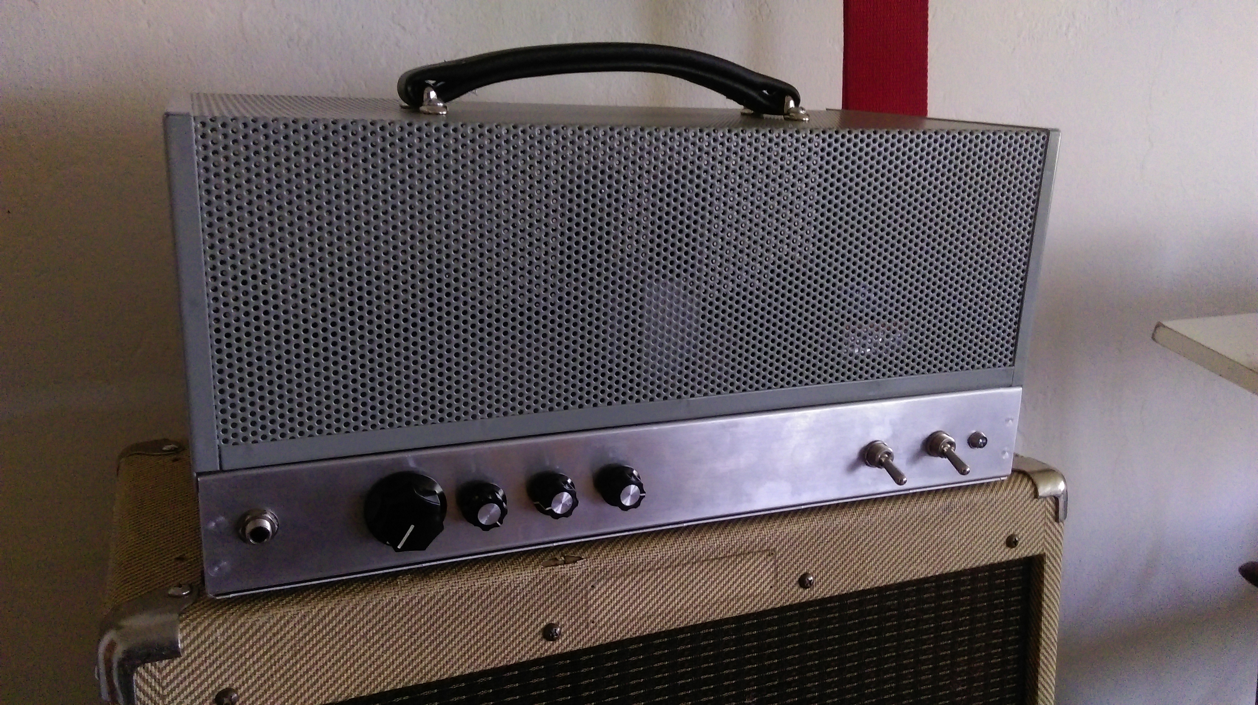
Well, 2017 is more than half over now. This means I should probably post something to get at least one post in for this year. I’ve been meaning to do a write up about this project for a while, but time isn’t as freely available as I would like it to be. Go figure. I had been wanting to try a push-pull tube amp build for years and scrapped together a design from parts I had lying around. I play a Gretsch G5265 baritone guitar with bass VI strings (this was its original configuration when I got it back in ’08), and I’ve had a hard time finding an amp that really suits the sound of the mini-humbuckers and it’s very deep tone. I decided to etch together a blackface Bassman-like amp with a tone stack capable of giving it the upper-mid range that it needs to bring out the high notes of the instrument. Unfortunately, I still haven’t gone through a rigorous analysis of the design other than some tone stack simulations in LTspice, but I’ll give out the schematic and details of the build.

6L6GC amp schematic

First off, the secondary voltage of the transformer should read around 300 V peak or around 600V peak-to-peak. Unlike a typical Bassman, it lacks a choke and the negative feedback resistor value is pretty large by comparison. I just swapped out values until I liked the sound and the oscillations stopped happening. I might swap this out with a 22k resistor again, but I can’t complain so far about the tone. There is one side of a 12AU7 (V2b) which is currently unused. I might make a simple phase shift oscillator of that later to make a tremolo circuit. If someone wanted to swap out 12AX7s in this design, the thing would be hella dirty and loud for a 40-ish watt amplifier (I still have to measure the actual wattage delivered to the load).

6L6GC amp tone simulation

Here is a plot of the magnitude of the tone stack simulation with the treble at noon, the bass at 9 o’clock, and the mid all the way up. The behavior of the stack is interesting as changing any one of the pots can have a sometimes dramatic effect on the position of the mid center frequency. This is one of the made drawbacks of passive tone stacks since the change in resistance of any potentiometer changes the transfer function for the network. However, the tone stack does lend itself to also listening to recorded music when setup properly. We’ve actually used this as a PA head in conjunction with a subwoofer which worked out really well. It’s bright nature actually seems to work well for vocals and low-mid while the sub picks up anything under 150 Hz or so.

6L6GC amp guts

I have a number of pictures that show how the layout progressed from right to left inside the chassis. Basically, I just started on the right side closest to the power transformer and worked towards the input. The biasing circuitry is towards the front of the amp by the large filter caps in the picture.

6L6GC tube glow

I was reading through Theory and Application of Electron Tubes [1] and discovered that the blue plasma color is actually caused by a spray of electrons from the cathode that actually overshoot the anode and slam into the glass. In the picture, you can see how the blue light only cover the area surrounding the big gray metal anode inside the glass. My new JJs that I put in there don’t have such an extreme blue color to them during operation.

Lastly, pictured above is the final build with the steel cage situated on top. The chassis is aluminum while the cage is steel. Both are manufactured by the fine folks at Hammond. I picked these up off CE Distribution’s website for a decent price. There’s definitely some room for improvement in the overall, but I really didn’t think it would work at all. I do think that it’s one of the nicest sounding amps I’ve ever owned regardless of the fact that I built it. I’ll post some sound samples eventually with some different instruments so anyone who stumbles upon this post can hear what the amp sounds like at lower volumes at least.

References
[1] Reich, H. (1944). Theory and Application of Electron Tubes. New York [usw.]: Mc Graw-Hill.

solid-state tremolo for tube amps…

i’ve have a CBS-era Fender Bantam Bass in for repair that looks like a bowl of spaghetti inside the chassis. it’s a slew of yellow wire spread from one side to the other that resembles the web of a drunken spider. the amp has been modified to include a tremolo, reverb, and an effects loop that replaces the bass channel in the amp. the tremolo circuit was originally a Weber kit, but someone ripped a couple of the pads off the PCB while trying to modify the mod. i just redesigned a tremolo circuit based upon a simple dual opamp LFO using the Weber’s rectifier as a guide to get voltage from the heater filament supply. i attached the output to an “Intensity” pot and wired it into the cathode of the second half of the initial 12AX7. The schematic below has node “A” highlighted to show where the output of the tremolo circuit was connect in the amplifier.

bantam_layout_01

this is the layout as i was laying my new designed tremolo into the existing circuit.

bantam_layout_02

this is the part of the original Weber tremolo where the last tech (careful with that soldering iron, Eugene!) attempted to modulate of the negative grid bias. though a sound idea, the circuit itself wound up acting more like a compression effect by changing altering the bias when signal was present. also, a solid-state tremolo like this won’t have much of an overall effect on negative grid biasing due mostly to it’s weak output. rails on the LFO is roughly +5.5V resulting in a good 2.25Vpk (1.5Vrms) signal which is hardly enough to be noticeable. i also tend to avoid using trem circuits that re-bias the output stage simply because it does seem to put undue stress on the tubes and surrounding components. it seems more efficient and makes more sense to me to modulate signals while they’re still small.

bantam_layout_04

cleaner and a little more manageable.

bantam_layout_05

and with a fine custom-made panel, the old Bantam looks and sounds more like a ’65 Super Reverb than ever before. granted, not all steps were taken to black-face the amp, but a few value substitutions were made to achieve more of a black-face tone.

Mistumin Valve Caster build…

a tube overdrive build for Anthony of the The New Diet and The Regular Fucked Up People. it’s my take on the Mitsumin valve caster with the values i tend to use and a Telefunken 12AX7. excuse the ugliness for this one is just the prototype.

four sections of clean vs. effected total.
[audio:http://abrammorphew.com/notes/wp-content/uploads/2013/02/tube_overdrive_sample_long_02.mp3|titles=Tube Overdrive sound sample]
1) high volume, no tone roll-off, and low gain
2) mid volume, high tone roll-off, and mid gain
3) mid volume, mid tone, mid gain
4) high volume, low tone, high gain

tube_od_proto_02

tube_od_proto_03

tube_od_proto_04

no. 5 re-appropriation…

no5_redesign

this is a re-appropriation of a Fender Frontman 15-B. it’s one 8″ speaker in a closed cabinet primarily designed as a really cheap bass amp to be included in starter packs. having gutted the amp a few years ago and replaced it with the contents from the No. 5 tube amp project, i got some time to rework the circuit into something more usable.

the additions include a tone stack, second gain stage, and a stand-by switch. the power amp is now wired as a pentode instead of a triode, and i didn’t feel it necessary to have a switch between the two modes. it still needs a little work to keep it from self-oscillating at high volumes. thanks to those guys who run AX84.com for their P1 project. it definitely helped the way i thought about redesigning the amp.

5W single-ended EL84 amp (before)

insides of a Fender 15B solid-state bass amp that i gutted and converted into a simple tube circuit. i constructed this several years ago, and it’s not been very functional as of late. it definitely needs a better chassis ground, and i’d like to add in a switch for triode/pentode operation as well as a tone stack. i’d also like to play around with some of the filtering design as a practice.

Ampeg SVT-CL Repair

here’s a 300 watt Ampeg SVT-CL that i had on the bench today. a much different kind of amp from the 70s models that i’ve been more accustomed to working on in the past. this one had no sound or output and the fault light would stay on constantly. i assumed right away that it must be circuit related. turns out that it was actually just drift in an old set of tubes that got so bad it caused the amp to fault. i switched the tubes around so that they could get a different set of voltages and then adjusted the bias until it stopped faulting. also replaced the 12AX7 phase inverter since it was showing signs of age. i figured it would help to at least have one known good in one of the most important spots. after that, i gave it a couple hours of play time with some solid signal just to make sure it didn’t drift again. a new set of 6550s should square out everything for another year.

No. 5 speaks.

and what a lovely voice it is. even through a Crate speaker (i’m saving the better speakers for when the testing phase is over). overall, i’d say a success for cheap transformers, Radio Shack parts, and a few pieces taken from a busted computer power supply.

audio notes: it was late, and i was annoying enough playing at midnight. the mic is sitting just above the speaker which was laying face up in a milk crate. i’m currently using a 100k audio pot, and i think it would fair better with a 1M. overall though, the amp is surprisingly quiet at mid volume. i still need to drill out the hole for AC connector, but it will come in due time. for now, it’s making sound and that’s a huge first step for me.