
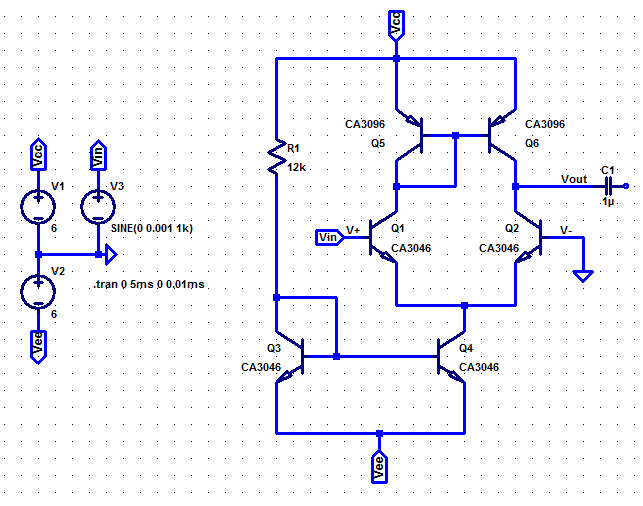
This is a circuit designed for a classroom project whereby the instructions were to “improve” a differential amplifier circuit. The differential amplifier design is essentially an exercise in understanding the inner workings of an opamp, and it effectively works in the same way. The figure below is a schematic for the differential amplifier without the cathode follower output stage. In the LTspice simulation, the input signal is connected to the V+ terminal and the V- terminal is connected to ground. There is no feedback loop between the output and either input terminal making this a high-gain open-loop configuration. However, adding a resistor from V- to ground and one from the output terminal to V- would accomplish the same results as a non-inverting opamp.
I wouldn’t say that adding a cathode follower “improves” the output stage of the amp. It was more an experiment in comparing different solid-state output stages with a vacuum tube stage operating at very low voltages. However, I will say that this thing sounded amazing with the couple of guitars I tested through it. Putting a potentiometer in the feedback network allowed me to play with different gain settings. It’s a very bright sound overall giving lots of high-end sparkle, but the breakup was quite remarkable. I suspect this might be a very usable configuration for a tube mic preamp or a number of audio applications. Hopefully, I will get an opportunity to revisit this before too long.
For those of you interested in the ins and outs of this experiment, you can download our full report here.