Author: abram

  • ARDUINO: Setting up a Gentoo development environment…

    if you’re reading this post, most likely you’re having issues with setting up Crossdev as mentioned on the arduino.cc site. i tried countless times to configure my system for AVR compiling that way, but it always failed compiling avr-libc and would never compile avr-g++ no matter how i applied the USE flags. in short, i had to manually compile the necessary environment and this article is so i don’t forget how that’s done. it seems there are only a smattering ink blot’s worth of people developing Arduino sketches under the Gentoo distribution, but this should work (in theory) for most any Linux distro out there since it’s all manual installation. if anyone happens to hit a snag during their installation, feel free to let me know.

    Download the tool chain…

    getting the right version is the key. some newer versions don’t play nice with ATMEL’s chips for whatever reason.

    1) BinUtils 2.20.1a: http://ftp.gnu.org/gnu/binutils/binutils-2.20.1a.tar.bz2
    2) GCC 4.3.6: http://gcc.petsads.us/releases/gcc-4.3.6/gcc-g++-4.3.6.tar.bz2
    3) AVR LibC 1.7.1: http://download.savannah.gnu.org/releases/avr-libc/avr-libc-1.7.1.tar.bz2

    these are the versions that both myself and Jose Moldonado in Spain have been able to run without problems.

    Additional downloads…

    you’ll need AVRDuDe. i installed it from source just to be safe, though i think the portage install is just as good.

    http://download.savannah.gnu.org/releases/avrdude/avrdude-5.11.tar.gz

    PREFIX and PATH

    this is how my system is setup.

    #PREFIX=/usr/i686-pc-linux-gnu/avr
    #export PREFIX
    #PATH=$PATH:$PREFIX/bin
    #export PATH
    

    make sure to do this FIRST. not modifying the PREFIX variable could potentially hose the whole system.

    Compiling…

    then you can start compiling binutils:

    # cd binutils-2.20.1a
    # mkdir obj-avr
    # cd obj-avr
    # ../configure --prefix=/usr/x86_64-pc-linux-gnu/avr --target=avr --disable-nls
    # make
    # make install
    

    then onto gcc…

    # cd gcc-4.3.6
    # mkdir obj-avr
    # cd obj-avr
    # ../configure --prefix=/usr/x86_64-pc-linux-gnu/avr --target=avr --enable-languages=c,c++ --disable-nls --disable-libssp --with-dwarf2
    # make
    # make install
    

    then avr-libc…

    # cd avr-libc-1.7.1
    # ./configure --prefix=/usr/x86_64-pc-linux-gnu/avr --build=x86_64-pc-linux-gnu --host=avr
    # make
    # make install
    

    Symlinking your libs and includes…

    now on my system, there was a /usr/avr folder that the Arduino IDE definitely looks in for the includes and additional libraries. i had to symlink two folders in order for the IDE to work.

    # ln -s /usr/i686-pc-linux-gnu/avr/avr/include /usr/avr/include
    # ln -s /usr/i686-pc-linux-gnu/avr/avr/lib /usr/avr/lib
    

    …and that was that. the latest Arduino IDE ran without a hitch.

    for more detailed information, go here: http://www.nongnu.org/avr-libc/user-manual/install_tools.html

  • SCHEMATIC: TL082 9V Active EQ…

    an experimental EQ circuit based of the TL082 datasheet. i modified it to use a 9V battery, but could probably still use some work in terms of efficiency… as most things. nothing is ever finished really. the mid portion has a pretty high quiescence. fine tuning, of course, can be done with the resistor values and more dramatic differences by adjusting the cap values. if you happen to build it, shoot me an email and let me know what you changed or decided to change.

    also keep in mind that the TL082 is a little noisy, so 6dB of highs will add in some noise. i kind of like it myself, but the TL072 is a better choice from what i understand.

  • SPICE: ngSpice plot test…

    nothing too special here. i’ve been practicing my SPICE skills and attempting to work with a single-supply active EQ circuit based on the TL082. further research of this chip has pointed out that the TL072 is better for audio applications, but it seems that the differences are pretty minuscule.

    here’s the spice code with the subcircuit that i downloaded off TI’s web site.

    * Spice netlister for gnetlist
    XU1 n7 	n2 	n1 	0 	n4 	TL082
    C1	n4	n6				10U
    C2	n5  n7				.1U
    RL	n6	0				1MEG
    R2 	n2 	n4 				10K
    R1	n2 	0				10K
    R3	n1	n7				10K
    R4	n7  0				3.3K
    V2 	n5	0 				SIN(0 1 1kHz)
    V1 	n1 	0 				9
    .TRAN 0.01ms 10ms
    .PLOT n5 n6
    .END


    * TL082 OPERATIONAL AMPLIFIER "MACROMODEL" SUBCIRCUIT
    * CREATED USING PARTS RELEASE 4.01 ON 06/16/89 AT 13:08
    * (REV N/A)      SUPPLY VOLTAGE: +/-15V
    * CONNECTIONS:   NON-INVERTING INPUT
    *                | INVERTING INPUT
    *                | | POSITIVE POWER SUPPLY
    *                | | | NEGATIVE POWER SUPPLY
    *                | | | | OUTPUT
    *                | | | | |
    .SUBCKT TL082    1 2 3 4 5
    *
      C1   11 12 3.498E-12
      C2    6  7 15.00E-12
      DC    5 53 DX
      DE   54  5 DX
      DLP  90 91 DX
      DLN  92 90 DX
      DP    4  3 DX
      EGND 99  0 POLY(2) (3,0) (4,0) 0 .5 .5
      FB    7 99 POLY(5) VB VC VE VLP VLN 0 4.715E6 -5E6 5E6 5E6 -5E6
      GA    6  0 11 12 282.8E-6
      GCM   0  6 10 99 8.942E-9
      ISS   3 10 DC 195.0E-6
      HLIM 90  0 VLIM 1K
      J1   11  2 10 JX
      J2   12  1 10 JX
      R2    6  9 100.0E3
      RD1   4 11 3.536E3
      RD2   4 12 3.536E3
      RO1   8  5 150
      RO2   7 99 150
      RP    3  4 2.143E3
      RSS  10 99 1.026E6
      VB    9  0 DC 0
      VC    3 53 DC 2.200
      VE   54  4 DC 2.200
      VLIM  7  8 DC 0
      VLP  91  0 DC 25
      VLN   0 92 DC 25
    .MODEL DX D(IS=800.0E-18)
    .MODEL JX PJF(IS=15.00E-12 BETA=270.1E-6 VTO=-1)
    .ENDS
    
  • Mellotronium revised…

    here’s an update on the new additions/approach to the Mellotronium. i’m attempting to redo the SD card routines once i get the functionality added. using the SD library just doesn’t work right when reading byte values at 8kHz. i’ve looked into the WaveHC library with the most success, but had to modify not to use an external DAC. a new wav file playing solution from the SD card will have to be found.

    without the clunky SD lib, program space has opened up… a lot of it in fact. now i’ve started using a wavetable. this video just has a single sine wave, but it’s modulate with the LFO and its seven different waveforms not to mention an amplitude modulating ADSR filter.

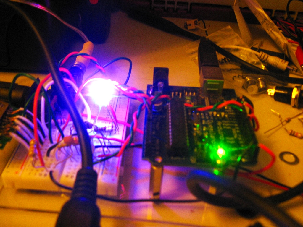
    the breadboard to the side contains an experimental active 2-band EQ (TLO82-based) which needs some work. if anyone has any experience with this, i would love to know why the schematic in the datasheet doesn’t work at all. i wound up having to recall the usage from a different schematic where you make a voltage divider from and peer it into the positive terminal on both opamps. it works… in a way. i think i’ve inverted the wave form or something strange. it also sometimes works better as a radio than an EQ which i think i like. it made for some interesting heterodyning.

  • mobile APRS setup…

    here’s a picture of my mobile APRS setup in the Jeep. it’s been a fun project from time to time. eventually, i plan on constructing a 2m vertical antenna to throw on the roof for better satellite reception while being mobile. i’m currently using a high-gain Comet mag-mount which is an excellent antenna. i was actually able to get out over 20 miles the other night on 146.52 with K5YLE using only 5 watts on the FT-60. for satellite reception, i’ll have to do a custom design.

    the setup uses the FT-60R packet cable design into my Gentoo Linux laptop (Samsung N210) running soundmodem and Xastir.

  • the Stirgiform PT2399 delay…

    two days worth of soldering and layout. it’s a combination of the Magnus Modulus and Rebote delay schematics. i couldn’t get the mixing circuit to really work from the Rebote schematic (an older version) without some serious distortion, so i just kind of reworked it on my own. here’s the schematic. i wouldn’t commit to it 100%, but it’s a start. tomorrow i’ll see if it level from bypass to effect works.

  • Arduino: LFO Generator

    here’s a treat for anyone that’s into the audio side of arduino. it’s an 8-bit two-timer based LFO Generator using timer 0/2 on an ATMega328p. i’m only using timer0 for output in this code. i’ve started implementing the LFO code into my 8-bit melotronium where timer2 is dedicated for the audio output. in the larger code base, timer0 just stores values in an unsigned integer that the other timer grabs and modulates the output mathematically. for now, this should be a good reference to anyone looking for the outline of an LFO with seven different wave forms.

    #define cbi(sfr, bit) (_SFR_BYTE(sfr) &= ~_BV(bit))
    #define sbi(sfr, bit) (_SFR_BYTE(sfr) |= _BV(bit))
    
    uint8_t sineTable[] = {
      127,130,133,136,139,143,146,149,152,155,158,161,164,167,170,173,176,178,181,184,187,190,
      192,195,198,200,203,205,208,210,212,215,217,219,221,223,225,227,229,231,233,234,236,238,
      239,240,242,243,244,245,247,248,249,249,250,251,252,252,253,253,253,254,254,254,254,254,254,
      254,253,253,253,252,252,251,250,249,249,248,247,245,244,243,242,240,239,238,236,234,
      233,231,229,227,225,223,221,219,217,215,212,210,208,205,203,200,198,195,192,190,187,184,
      181,178,176,173,170,167,164,161,158,155,152,149,146,143,139,136,133,130,127,124,121,118,
      115,111,108,105,102,99,96,93,90,87,84,81,78,76,73,70,67,64,62,59,56,54,51,49,46,44,
      42,39,37,35,33,31,29,27,25,23,21,20,18,16,15,14,12,11,10,9,7,6,5,5,4,3,2,2,1,1,1,0,0,0,
      0,0,0,0,1,1,1,2,2,3,4,5,5,6,7,9,10,11,12,14,15,16,18,20,21,23,25,27,29,31, 33,35,37,39,42,
      44,46,49,51,54,56,59,62,64,67,70,73,76,78,81,84,87,90,93,96,99,102,105,108,111,115,118,121,124
    };
    
    uint8_t tWave = 128;
    uint8_t sWave = 255;
    uint8_t ruWave = 128;
    uint8_t rdWave = 128;
    uint8_t rWave = 128;
    
    int   i = 0;
    int   rate;
    int   waveform;
    byte  d = HIGH;
    
    void setup() {
      pinMode(3, OUTPUT);
      setupTimer();
      OCR0A = 128;
    }
    
    void loop() {
      waveform = map(analogRead(0),0,1023,1,7);
      rate = map(analogRead(1),0,1023,255,0);
      OCR0A = rate;
    }
    
    ISR(TIMER0_COMPA_vect) {
      if(i == 255) i = 0;
      switch(waveform) {
        case 1:
          analogWrite(3,sine(i));
        break;
        case 2:
          analogWrite(3,triangle(i));
        break;
        case 3:
          analogWrite(3, square(i));
        break;
        case 4:
          analogWrite(3, rampUp(i));
        break;
        case 5:
          analogWrite(3, rampDown(i));
        break;
        case 6:
          analogWrite(3, rand(i));
        break;
        case 7:
          analogWrite(3, white(i));
        break;
      }
      i++;
    }
    
    void setupTimer() {
      cli();
    /*--- TIMER2 CONFIG ---*/
      sbi(TCCR2A,WGM20);
      sbi(TCCR2A,WGM21);
      cbi(TCCR2A,WGM22);
     
      sbi(TCCR2B, CS20);
      cbi(TCCR2B, CS21);
      cbi(TCCR2B, CS22);
    
      sbi(TCCR2A,COM2B1);
      cbi(TCCR2A,COM2B0);
       
     /*--- TIMER0 CONFIG ---*/ 
      cbi(TCCR0B,CS00);
      cbi(TCCR0B,CS01);
      sbi(TCCR0B,CS02);
     
      sbi(TCCR0A, COM0A1);
      cbi(TCCR0A, COM0A0);
        
      cbi(TCCR0A, WGM00);
      sbi(TCCR0A, WGM01);
      cbi(TCCR0A, WGM02);
    
      cbi(TIFR0,OCF0A);
      sbi(TIMSK0,OCIE0A);
      sei(); 
    }
    
    int sine(int i) {
      return sineTable[i];
    }
    
    int triangle(int i) {
      if(tWave >= 255) d = LOW;
      if(tWave <= 0) d = HIGH;
      if(d == HIGH) tWave++;
      if(d == LOW) tWave--;
      return tWave; 
    }
    
    int rampUp(int i) {
      ruWave++;
      if(ruWave > 255) ruWave = 0; 
      return ruWave;
    }
    
    int rampDown(int i) {
      rdWave--;
      if(rdWave < 0) rdWave = 255;
      return rdWave;
    }
    
    int square(int i) {
      if(i >= 128) sWave = 255;
      if(i <= 127) sWave = 0;
      return sWave;
    }
    
    int rand(int i) {
      if(i == rWave) rWave = random(255);
      return rWave;
    }
    
    int white(int i) {
      return random(255);
    }
    

    Update: Here's my current code for the ATTiny85. It's not exactly bug-free as there seems to be some issue with latch-up when the speed of the LFO is high. This of course could be remedied by limiting the map() function's minimum value. I can't remember off hand if there are any other issues. Good power supply and output filtering is definitely needed to reduce noise in any additional stages of the circuit. At some point, I'll just make a separate post detailing my tremolo effect circuit in detail (so many projects and so little time!). Until then:

    /*
     * Title: LFO Generator for ATTiny85 v0.12
     * Author: Abram Morphew
     * Date: 09.19.2016
     * Purpose: Low frequency oscillator with wave output controls
     */
    
    #define cbi(sfr, bit) (_SFR_BYTE(sfr) &= ~_BV(bit))
    #define sbi(sfr, bit) (_SFR_BYTE(sfr) |= _BV(bit))
    
    uint8_t sineTable[] = {
      127,130,133,136,139,143,146,149,152,155,158,161,164,167,170,173,176,178,181,184,187,190,
      192,195,198,200,203,205,208,210,212,215,217,219,221,223,225,227,229,231,233,234,236,238,
      239,240,242,243,244,245,247,248,249,249,250,251,252,252,253,253,253,254,254,254,254,254,254,
      254,253,253,253,252,252,251,250,249,249,248,247,245,244,243,242,240,239,238,236,234,
      233,231,229,227,225,223,221,219,217,215,212,210,208,205,203,200,198,195,192,190,187,184,
      181,178,176,173,170,167,164,161,158,155,152,149,146,143,139,136,133,130,127,124,121,118,
      115,111,108,105,102,99,96,93,90,87,84,81,78,76,73,70,67,64,62,59,56,54,51,49,46,44,
      42,39,37,35,33,31,29,27,25,23,21,20,18,16,15,14,12,11,10,9,7,6,5,5,4,3,2,2,1,1,1,0,0,0,
      0,0,0,0,1,1,1,2,2,3,4,5,5,6,7,9,10,11,12,14,15,16,18,20,21,23,25,27,29,31, 33,35,37,39,42,
      44,46,49,51,54,56,59,62,64,67,70,73,76,78,81,84,87,90,93,96,99,102,105,108,111,115,118,121,124
    };
    
    uint8_t tWave = 128;
    uint8_t sWave = 255;
    uint8_t ruWave = 128;
    uint8_t rdWave = 128;
    uint8_t rWave = 128;
    
    int   i = 0;
    int   rate;
    int   waveform;
    byte  d = HIGH;
    const uint8_t output = 1;                       // output pin #6 on ATTiny85
    
    void setup() {
      setupTimer();
      pinMode(3, INPUT);
      pinMode(2, INPUT);
      pinMode(output, OUTPUT);
      OCR0A = 128;
    }
    
    void loop() {
      waveform = map(analogRead(2),0,1023,1,6);
      rate = map(analogRead(3),0,1023,255,0);
      OCR0A = rate;
    }
    
    ISR(TIMER0_COMPA_vect) {
      if(i == 255) i = 0;
      switch(waveform) {
        case 1:
          analogWrite(output,sine(i));
        break;
        case 2:
          analogWrite(output,triangle(i));
        break;
        case 3:
          analogWrite(output, square(i));
        break;
        case 4:
          analogWrite(output, rampUp(i));
        break;
        case 5:
          analogWrite(output, rampDown(i));
        break;
        case 6:
          analogWrite(output, rand(i));
        break;
        case 7:
          analogWrite(output, white(i));
        break;
      }
      i++;
    }
    
    void setupTimer() {
      cli(); 
     /*--- TIMER0 CONFIG ---*/  
      TCCR0A = 0b10000011;
      TCCR0B = 0b00001010;    // last 3 bits set prescalar for Timer0
    
      cbi(TIFR,OCF0A);
      sbi(TIMSK,OCIE0A);
      sei(); 
    }
    
    int sine(int i) {
      return sineTable[i];
    }
    
    int triangle(int i) {
      if(tWave >= 255) d = LOW;
      if(tWave <= 0) d = HIGH;
      if(d == HIGH) tWave++;
      if(d == LOW) tWave--;
      return tWave; 
    }
    
    int rampUp(int i) {
      ruWave++;
      if(ruWave > 255) ruWave = 0; 
      return ruWave;
    }
    
    int rampDown(int i) {
      rdWave--;
      if(rdWave < 0) rdWave = 255;
      return rdWave;
    }
    
    int square(int i) {
      if(i >= 128) sWave = 255;
      if(i <= 127) sWave = 0;
      return sWave;
    }
    
    int rand(int i) {
      if(i == rWave) rWave = random(255);
      return rWave;
    }
    
    int white(int i) {
      return random(255);
    }
    
  • Arduino: the 8-bit Mellotronium prototype

    i’ve been pretty Arduino obsessed over the past month. i got in my head this idea about building a midi-controlled digital sampler that uses SD cards for storage after thumbing through the Arduino Cookbook and have finally started to make some headway on the project.

    there were some major obstacle to overcome, unfortunately. the first came about when i had some trouble loading the larger libraries (e.g. MIDI.h, SD.h). i spent days trying to figure out what the problem was and even went so far as to update the bootloader to use optiboot. it turned out to be the version of GCC that i was using to compile my sketches. the toolchain setup on Gentoo is no easy task, so i went ahead and just compiled it manually. for those of you tempting to use develop AVR software in a Linux environment, i’d recommend the avr-libc install guide as your path to unbridled success. i myself could never get cross-dev to work with out failing and it needs certain USE flags which it just always overrode when i specified them.

    from then on, things were pretty standard. i was able to load SD.h and begin reading files from the card. i used simple voltage dividers to convert the ATMega328’s 5v logic to the SD’s 3.3v like the standard schematic shows and then hacked up the PCMAudio Library to work as i’ve wanted. i borrow some of the techniques from Max’s article on generating real-time audio using PCM. much different than my overall goal, but extremely educational. if you’re baffled by the ATMega328’s use of PWM as i was, Ken Sherif’s article on PWM will clear all that up.

    the code’s not worth posting at the moment. it’s a commented out mess of gray. i’ll most likely post it (for my own sake) when i’ve got more of the kinks worked out.

  • Arduino: second verse, same as first… sort of

    well, not really. feeble attempt and making some sort of microprocessor controlled tempo clock, but a good exercise in the ATMEGA328s finicky behavior. don’t ask me what that squeal is. i think it comes from the way the input was wired up (mistaking the second sleeve as a synonym for ground) coupled with the PWM stream not having a negative offset, but who knows. eventually, i’ll move off the tone() crutch and start working with more interesting DSP. it’ll be nice to start using some of the memory on the chip.

    i will also post the schematic for the delay pedal once i’ve got the values i want in it. i won’t have any time nor tools to tear into it until next week though.