
this is an experimental circuit i threw together today. i’ve been working on getting a VOX circuit to work with the Yaesu FT-60R (VX-3R, VX-5, etc.) and Soundmodem on the ol’ Gentoo box. it’s working well, but test packets have been a little iffy.
this is an experimental circuit i threw together today. i’ve been working on getting a VOX circuit to work with the Yaesu FT-60R (VX-3R, VX-5, etc.) and Soundmodem on the ol’ Gentoo box. it’s working well, but test packets have been a little iffy.

this is an older build now, but i wanted to post it while i’ve been on the subject to record the process. believe it or not, i still have some work to do on this one. i used a TL082 as a buffer for the mixing circuit. getting the gain set to my taste has been the toughest part. this one (unlike the last) is a bit low. it will all come in due time though. i’ve produced two solid builds this week (though really just debugging this one and one from scratch), and i’ll consider that a productive week.

a forced contract job for Ryan of Falcon Scott. he’s been having some issues finding an overdrive suitable to his hollow-body guitar. i just got a lot of BS170s and thought this might do the trick. the distortion is pretty squared off on the oscilloscope and crunchy. the left pot is post volume while the right biases the BS170. overall, it sounds pretty good and that’s saying a lot coming from someone who isn’t much into “distortion” (personal bias does make a difference. hah).
a big thanks to Jack Orman at Musique.com for laying out the basis. i modified his schematic a bit to get the “best” results for my ear, but i couldn’t have done it without his work.

ever wanted to see how that 2N2222 might hold up as a linear RF amplifier? here’s a handy feature of ngSpice that i found recently. i’m rather new to ngSpice and at first was somewhat frustrated by its differences from other SPICE variants. however, i’ve earned a deep appreciation for it and its integration with the gEDA suite.
V1 n1 0 sffm(2 24 10k 5 1k)
.tran 0.01ms 2ms
.plot n1
the above code generates the waveform seen above. the corresponding values in the sffm() function run something like this.
| Parameters | Default value | Unit |
|---|---|---|
| Vo (offset) | Ampere or Volt | |
| Va (amplitude) | Ampere or Volt | |
| Fc (carrier frequency) | 1/Tstop | Hz (Hertz) |
| Mi (modulation index) | ||
| Fs (modulation frequency) | 1/Tstop | Hz (Hertz) |
an older video, but one i’ve been wanting to post for some time. this is Alex Wilson of Son Cats playing on one of the several cigar-box amps i’ve constructed. this one, in particular, had one of the best sounds during the more work-with-what-is-available days. i thought the video was a great demo of an application best suited for a small 1/2 watt amp. thanks, Alex.
a good rule of thumb pulled from this forum thread (http://www.electro-tech-online.com/general-electronics-chat/39339-mosfet-vs-bjt.html):
MOSFETs can generally switch faster (they certainly require less complex and less power to drive their gates). But if I’m not mistaken, BJTs designed for the task can switch very very fast since they have no gate capacitance to charge and can also operate in quasi-saturation mode for even faster switching at the expense of conduction efficiency. MOSFETs have less losses when used as a switch at “lower” voltages (lower as in industry’s definition which is <~200V).
MOSFETs act like a resistor when on while BJTs act more like diodes. The resistance can be modified by changing the “dimensions” of the MOSFET while the BJT’s “diode voltage drop” can’t be changed so easily unless the materials are changed. THis tends to make MOSFETs have less losses at the lower voltages but also means MOSFETs can be paralleled since current imbalances will cancel out.
With parallel BJTs, the best BJT will hog the current from the other “not so good BJTs” and burn out and the cycle repeats with the remaining BJTs until they are all burned. This is similar to parallel diodes. You can correct for imbalances by manually tuning resistors in series with each BJT, but for power applications that’s needing massive resistors and wasting lots of power.
thanks guys…
a little improvisation i did after improving the LFO phase modulation and arpeggiator functions of the Mellotronium: an ATMega328P-based mirco-synthesizer. there are plenty of improvements to be made, but it’s surprising how much you can make of these microcontrollers do. combined with a Roland RC-50, it’s music composition on the fly.
you’ll have to excuse the loud hissing noise. apparently the power supply of my netbook isn’t exactly quiet. it sounds a lot better using the battery pack or the wall wart.
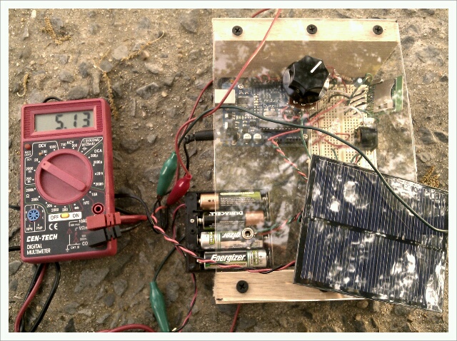
the micro-synthesizer is getting fitted to draw it’s power from the sun via a 6V 200mA solar cell. it’s pretty impressive what the sun along with a cheap collection of photovoltaic cells can do.


the need for small and portable amplifiers has arisen mainly by a desire to come up with some sort of all-purpose busking amplifier. here is the first screen shot of the output from the preamp section. the entire amplifier is powering an Eminence Beta-12LTA off of a mere 6V. don’t ask me how. it took a while to find the right combination of resistors for the TL082 to run stable at such a low voltage. it’s also surprisingly loud being that it’s about 26V away from the recommended supply (±16V). i’ll probably be posting a schematic soon.