Author: abram

  • Ampeg SVT-CL Repair

    here’s a 300 watt Ampeg SVT-CL that i had on the bench today. a much different kind of amp from the 70s models that i’ve been more accustomed to working on in the past. this one had no sound or output and the fault light would stay on constantly. i assumed right away that it must be circuit related. turns out that it was actually just drift in an old set of tubes that got so bad it caused the amp to fault. i switched the tubes around so that they could get a different set of voltages and then adjusted the bias until it stopped faulting. also replaced the 12AX7 phase inverter since it was showing signs of age. i figured it would help to at least have one known good in one of the most important spots. after that, i gave it a couple hours of play time with some solid signal just to make sure it didn’t drift again. a new set of 6550s should square out everything for another year.

  • Jeep XJ: no start, no spark, resolved!

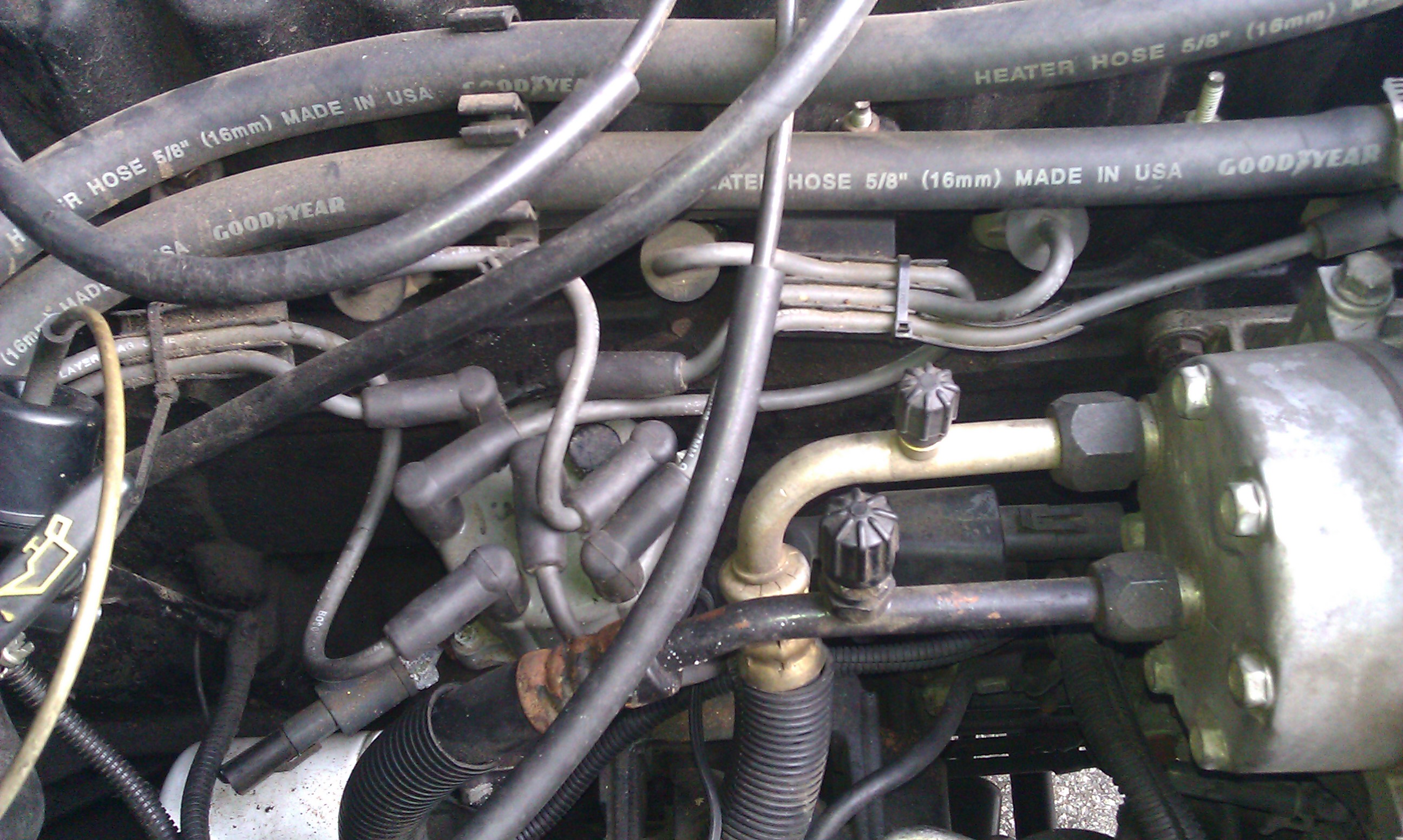
    after more than two weeks of not being able to start up the XJ, i was finally able to resolve the issue. turns out the ignition coil had gone bad. the Haynes manual gave guidelines for checking the resistance between the primary and secondary coils which all checked out with the coil. it was until i was able to get Bethany to turn the engine over while i used a multimeter to measure voltage coming in at the connector to the coil that i realized the coil was faulty. got a BWD coil at the auto parts store for $36, and it fired right up… once.

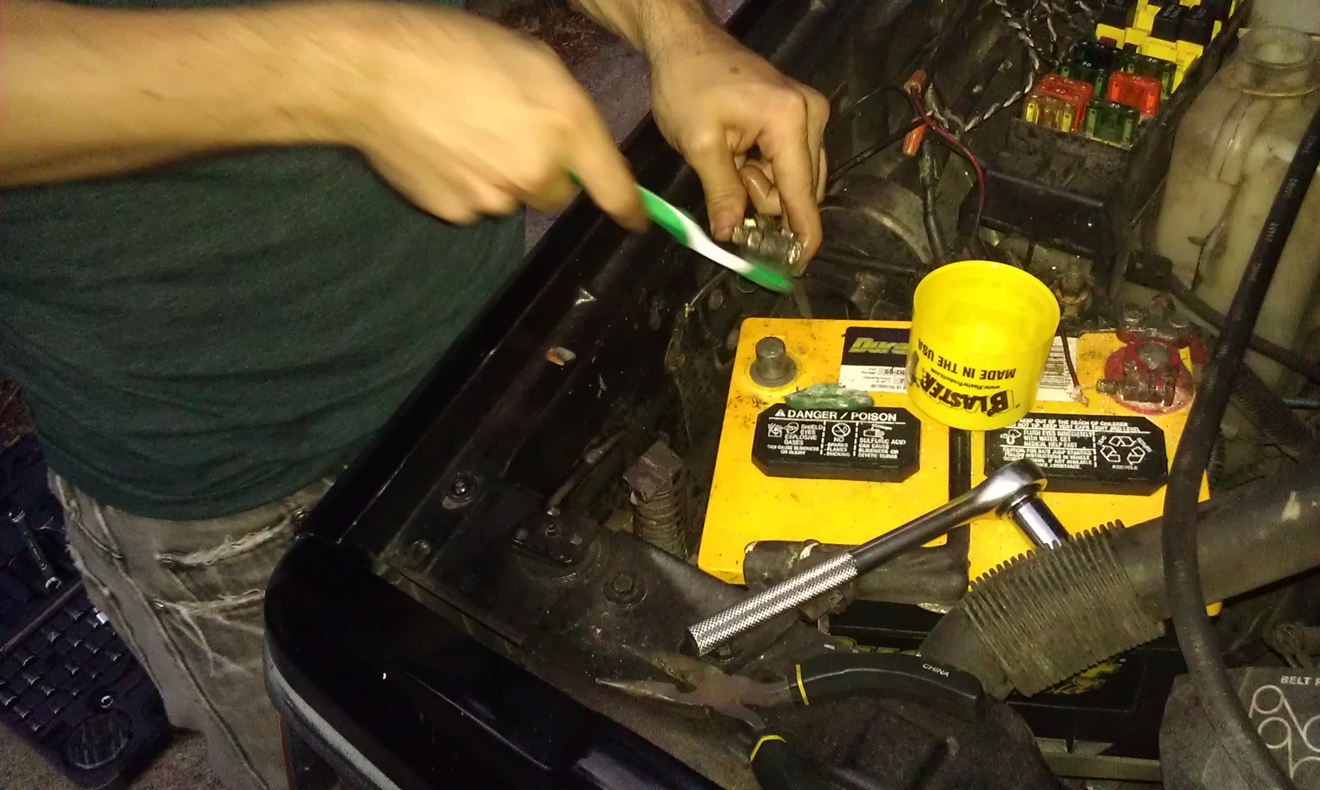
    after i shut the engine off, it wouldn’t turn over. i would turn the key, and the whole dashboard, overhead lights, and everything electrical would go dead. i’d pull out the key, wait a minute, reset the number 10 fuse in the fuse box under the steering column, and the power would come back. i’d try to start again and hear a “click” from the starter and all dead again. the problem was related to the corroded battery terminals which required me to clean them off with some Blaster and a toothbrush. after that, it’s fired up consistently though i plan on replacing the battery terminals soon enough.

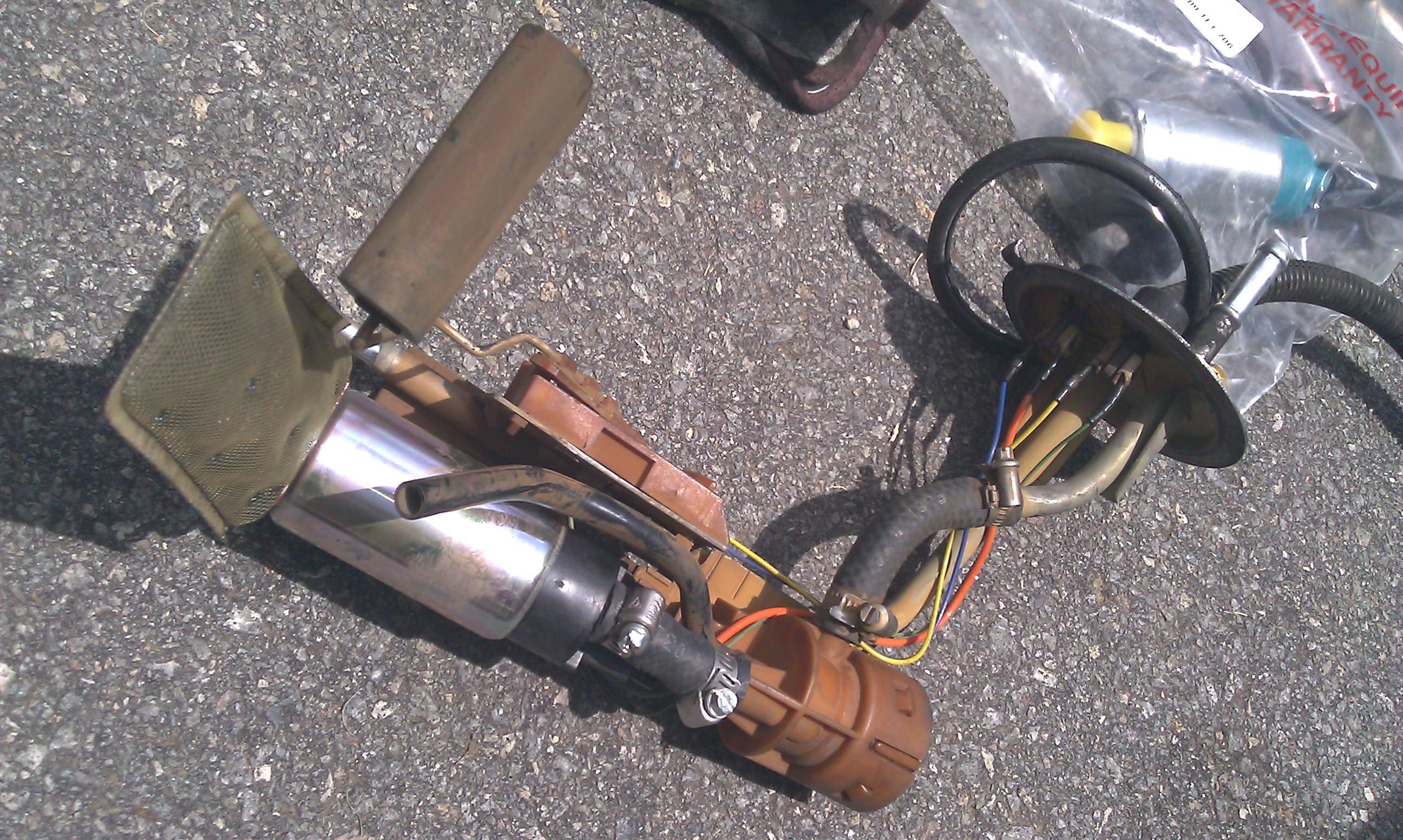
    i also wound up replacing the fuel pump which need to be replaced due to faulty check valves. the pump had only been in there for a little over a year (a 30k mile year) but was already having problems (Airtex?). pictured is the whole assembly with the replacement part in the plastic bag in the background.

  • PT2399: nuances…

    i’ve been wrapped up in Jeep repair lately as there’s some sort of issue prevent the beloved XJ from firing up. i have, however, in the meantime had some time to work through my initial modulation tests on this version of the PT2399 circuit and nail down a lot of the bugs.

    the initial problems were stabilizing the LFO and purging the noise from the chip. as you well know from the datasheet, the PT2399 has very little storage space. it also makes a lot of racket on the output of pin 14. i was able to use 2nF caps on the input to really filter some of that out and get the thing pretty quiet. the LFO problems were locked down thanks to the EchoBase schematic. the final draft will include an SPDT which will switch between the square and triangle wave. the audio test features only the triangle side of things.

    as for the audio, the first part is long delay with light modulation and moderate rate. the second is short delay with slow modulation, and the last is kind of a slap-back delay with faster modulation.

    i’m really looking forward to getting this one off the breadboard and into a usable stompbox. thanks to all of those people at DIY Stomp boxes who post information. it’s been a big help.

  • initial test of a modulated PT2399 circuit…

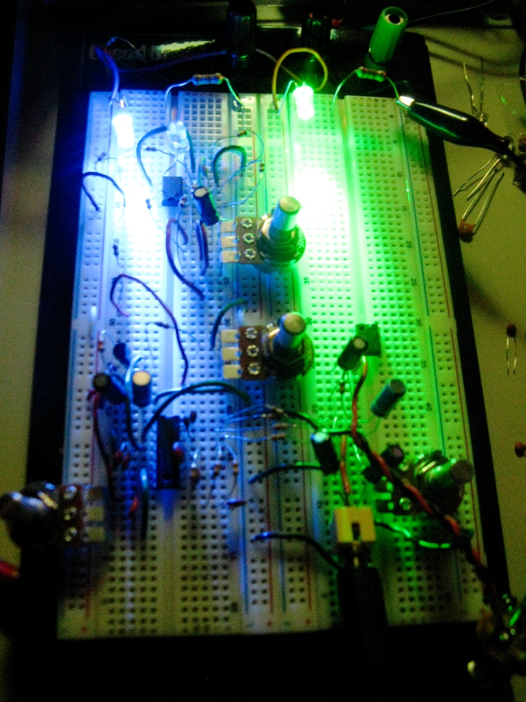
    a breadboard version of some PT2399 modifications i’ve been working on. there are a lot of DIY schematics that utilize the PT2399 (Magnus Modulus, Echo Base delay, Rebote, etc.). i’ve been interested at trying my hand at modulation techniques recently. i made a simple LFO circuit based on the findings mentioned in a previous post. i used some techniques out lined in some of the schematics floating out there to attempt to modulate the delay time of the chip. i wouldn’t say i’ve got it to work perfectly, but it’s definitely doing what i had hoped.

  • MOSFET overdrive… final build?

    i might add some labels for the pots and contact info, but it’s done for the most part.

  • simple LFO circuits…

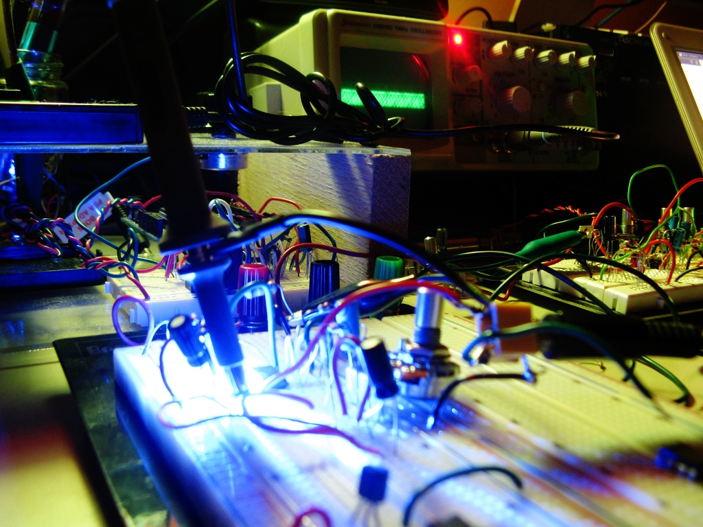
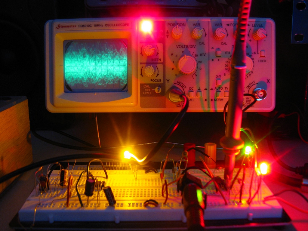
    i was reading over this thread on diystompboxes.com about building an analog LFO circuit for some wild noise idea i’ve got brewing in the back of my head. i started messing around with some of the schematics on there and got a drifting saw wave out of it after a while. i was trying to take a picture of the wave itself on the oscilloscope which obviously didn’t turn out all that well. so many breadboards. yeesh.

  • TDA2040 PCB layout…

    backlit PCB layout of the TDA2040 solid-state amp i’ve been working on. i’m still using perf boards until i wrap my head around designing PCB layouts in EagleCAD. i do a lot of work in the dark.

  • TDA2040-based amp schematic with EQ…

    well here’s the first draft of the simplest medium powered solid state design i could muster. TL082 can easily be substituted with a TL072 which is probably better anyhow (i just have all these TL082s laying around). the power supply i’m using more like 14-15V. both ICs should easily be able to handle up to 20V and that would allow for louder operation, but i think 15V is safe. all the resistors are 1/8W minus R20 which is 1/4W.

  • Sinometer 10MHz oscilloscope…


    simple. cheap. a thing of beauty to add to the ol’ workbench.