
a close-up picture of the guts of a JJ EL84 with all it’s grids exposed. such a seemingly odd and fascinating device.
a close-up picture of the guts of a JJ EL84 with all it’s grids exposed. such a seemingly odd and fascinating device.
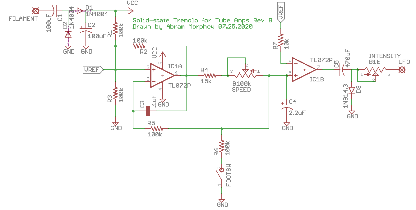
i’ve have a CBS-era Fender Bantam Bass in for repair that looks like a bowl of spaghetti inside the chassis. it’s a slew of yellow wire spread from one side to the other that resembles the web of a drunken spider. the amp has been modified to include a tremolo, reverb, and an effects loop that replaces the bass channel in the amp. the tremolo circuit was originally a Weber kit, but someone ripped a couple of the pads off the PCB while trying to modify the mod. i just redesigned a tremolo circuit based upon a simple dual opamp LFO using the Weber’s rectifier as a guide to get voltage from the heater filament supply. i attached the output to an “Intensity” pot and wired it into the cathode of the second half of the initial 12AX7. The schematic below has node “A” highlighted to show where the output of the tremolo circuit was connect in the amplifier.
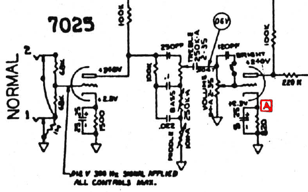

this is the layout as i was laying my new designed tremolo into the existing circuit.

this is the part of the original Weber tremolo where the last tech (careful with that soldering iron, Eugene!) attempted to modulate of the negative grid bias. though a sound idea, the circuit itself wound up acting more like a compression effect by changing altering the bias when signal was present. also, a solid-state tremolo like this won’t have much of an overall effect on negative grid biasing due mostly to it’s weak output. rails on the LFO is roughly +5.5V resulting in a good 2.25Vpk (1.5Vrms) signal which is hardly enough to be noticeable. i also tend to avoid using trem circuits that re-bias the output stage simply because it does seem to put undue stress on the tubes and surrounding components. it seems more efficient and makes more sense to me to modulate signals while they’re still small.

cleaner and a little more manageable.

and with a fine custom-made panel, the old Bantam looks and sounds more like a ’65 Super Reverb than ever before. granted, not all steps were taken to black-face the amp, but a few value substitutions were made to achieve more of a black-face tone.
I’ve seen a lot of the same complaints on various forums regarding these amps. Basically, the amp starts to get noisy and the occasional arcing can be heard through the speaker. The problem seems more exaggerated when using the tremolo circuit which is just a phase-shift LFO modulating the negative grid voltage. I’m not so sure that the blue 1/2 watt resistors inside the amp are not really metal film despite their appearance (**UPDATE** I’ve recently seen some evidence that arcing tends to happen more often in metal-film resistors. I’m not sure about how correct this is, but it would make sense in this amp). If you find yourself working on amp with these sort of issues, here is what I did to alleviate some of the nasty pops.
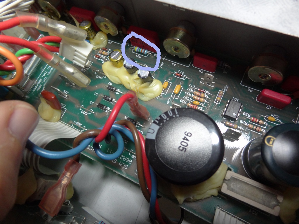
On the main board, change R34 from 475k to a 1M 1/2 watt resistor. Also change R8 (pictured below) from 221k to 270k. This will lower the the overall voltage swing on the grid preventing so much stress to the power tubes.
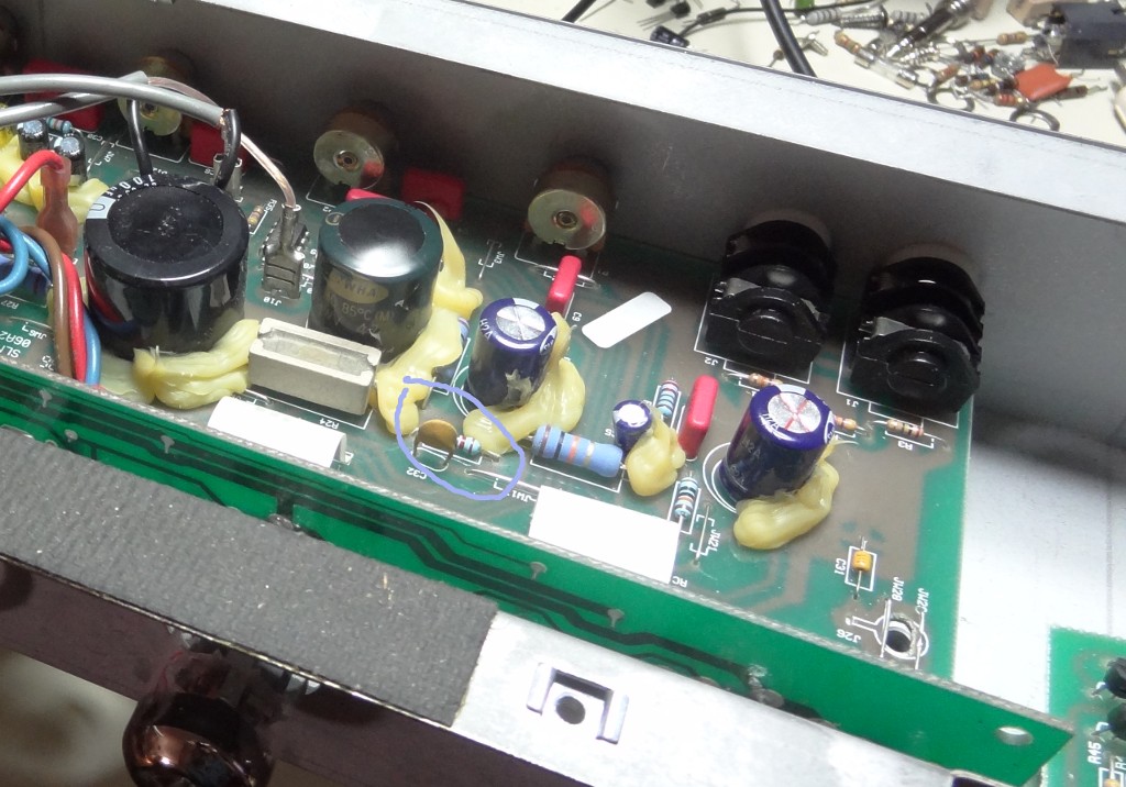
On the second board (the one that has the tube sockets), you’ll probably want to change out the metal-film resistors just to make sure they don’t start arcing. You can always tap them with a chopstick and listen for any pops in the speaker to determine if they are bad or not. I apologize for the lack of a picture, but there aren’t many components on the board. You should be able to find them all right in the middle grouped together.
R15 & R16: 100k
R17 & R18: 220k
R19 & R20L 22k
For this amp, the speaker was replaced with a 12″ Jensen C12N. The thing cleans up pretty nice and has a sound not unlike other true vintage Ampegs that I’ve heard.

just a copy with a homebrew 2m ground plane antenna on the roof top with the FT-60. pretty surprising results considering the antenna isn’t even tuned for 137MHz.

kind of a goofy experiment, but really useful. i’ve had a lot of LM335Zs laying around for a while. my christmas present this year was a new Arduino Mega 2560 board that i’ve hardly had a chance to do anything with. using the lovely Space Tinkerer’s blog and the good ol’ TVOut library, i turned a thrift store bargain into a fancy CRT monitor that reports the ambient temperature on the work bench.

a practice in designing an oscillator. this particular circuit employs a 2N2222A transistor on 6 volts. i used this Electronic-Tutorials.ws page to design the circuit. there were many reasons for this experiment, but the most immediate was to act as a simple CW practice oscillator. the final circuit looks something like the following.


