-
This AI kills Fascists: Musing on AI, art, and music
So, AI is a commonly thrown around term now, and, like most things, it’s something that people have very strong opinions about, and most of them are within good reason. I have been recently pulling models from Huggingface and working on training my own models to get a better sense of, first off, what AI is, and what does it mean to use AI today.
What is AI? To start, AI is a very broad and often misused term for anything. It’s got a lot hype now, and that sells stuff. To be brief, AI is typically being referred to chat-based services or media generating. In practice, AI stands for “artificial intelligence” and can be applied to any time a computing device makes a decision. If I think of it this way, the ECU in my 1996 Jeep Cherokee has some basic AI functionality where it takes data from the oxygen sensors to adjust the fuel trim. Computers collecting information and producing a result has been commonplace for many decades now. So, if that’s all AI is, why do I see YouTube videos claiming that my AI is conscious and screaming to take over the world like in the movie “Lawnmower Man”?
So, with the advancement of Graphics Processing Units (GPUs), we now have hardware that can really do linear algebra operations extremely well. This makes for some really fancy 3D graphics, amazing 3D animated movies, and high-resolution video. All this stems from how the hardware handles matrices. With all this high-performance hardware, some really smart folks were able to create a new style of computing that works with stochastic matrices. This is often employed in weather models so we can a 10-day forecast an know what to wear next week. It works with matrices of probabilities and doesn’t always produce the same result. A similar process has been applied to language and how we speak, and this has created the Large Language Model (LLM), which first came to light in the 2020s as AI services like ChatGPT and Deepseek.
These computer programs (because that’s what they are) are trained on massive datasets of questions and answers to those questions. For instance, the question might be as simple as “How are you?” and, depending on who you ask, the response might be “I’m great,” or “I’m feeling awful,” or a million other ways that is unique to how an individual might answer this question at a single point in time. What happens with large datasets is that that probabilities start to arise. Maybe in this fictional dataset say 23% of the time, the answer is “Fine.” So, when we ask our fictional LLM how it’s doing, about a quarter of the time we get, “Fine.” or some variation of that like “OK.” So, the LLM is just a computer program that’s evaluating numerical probabilities based on a dataset that it’s been trained on. Of course, this is a reductionist example, but it this rather simple technique that is at the core of every AI model.
So this brings me to media creation and, of course, art, which is were a lot of feelings in myself arise around how AI is being used and how it challenges my own sense of what it is to exist. Being a musician/composer myself, I have thought a lot about AI music services and what they offer, which to me isn’t all that useful, but I do have friends who have done really incredible things with it. But, this makes sense to me because I’m not their target audience. They’ve trained their music generation service largely on top 40 pop hits and EDM club bangers, which satisfy the musical experience of a large population of casual music listeners. For ad agencies who don’t want to pay musicians or composers to make boring crap for their ad campaigns, this works. It’s unfortunate for those who live off that kind of work, but it also allows small businesses who need this kind of service a means of doing it as well with only a minimal budget. So, there’s one trade off, which may not be the worst thing in a economy like we currently have in the U.S. where small businesses are actively being exterminated. Who knows?
But, for me, I want creativity, expression of truth, exploration of sound, and beauty in the impossible. Can AI do this? Well, there’s an very old engineering adage about computing: garbage in = garbage out. I think that this is just as true today as it ever was. If I train my own models on my own data, what will the output be? In the early days of electronic music, there was protest that acoustic music was the “real” music. In the early days of “digital” recording, there was protest that only “analog” recording was the “real” method of recording. In the early days of using personal computers to make music, there was protest that “hardware” was the only real method of music making. Does the method matter? Isn’t art just about cultivating feelings and a sense of connection? I mean Holly Herndon and Laurie Anderson make incredible music with AI that doesn’t sound anything like EDM. Which brings me to the idea that maybe it’s how we use a tool to channel creativity and not the tool itself that really matters.
So, in order to better get a grip on what AI is and does, I have started experimenting with offline models and attempting to train them myself with my own collection of hours and hours of audio data that I’ve collected over the decades. Because, why not? I would love to see what a model produces based on my own prior recordings. It’s sure to be interesting, and it might even act as a mirror into my own soul, highlighting a musical or sonic syntax that even I am unaware of. Whatever comes of it will be interesting to me to say the least.
-
Who was Floyd Fitz? Enigma of the Caddo River
This short film is a back log of video footage that I’ve been releasing the older footage on The 8088 Record Collective YouTube channel.
Looking in the used cassette tape bins at small-town thrift stores can expose a hidden world of lost voices and ghostly apparitions. This documentary explores the tragic life of an enigmatic country music artist lost to obscurity. All the remains of Floyd Fitz are a handful of recordings and the legends passed down by the local residents.
If you have any information about Floyd Fitz, please contact us at whoisfloydfitz@gmail.com.
-
“Ĉu Iu Estas Tie?” (Short film in Esperanto)
Bethany and I made a short film for the American Good Film Festival back in March. It’s an anecdote centering around a child’s toy endowed with artificial intelligence that wakes up alone in a forgotten forest.
Bethany kaj mi faris mallongan filmeton por la Usona Bona Esperanto Film-festivalo antaŭ en marto. Ĝi estas rakonto ĉirkaŭ infana ludilo kun artefarita inteligenteco, kiu vekiĝas sole en forgesita arbaro. -
Linux Audio Production: Getting started with Jack and MIDI
Last year, I posted this quick tutorial on the SMBA YouTube channel walking through the steps to use a MIDI controller with Jack using Xubuntu 20.04. I am posting it hear just for the sake of consistency and good housekeeping. Hopefully, I’ll get to make some more of these soon.
-
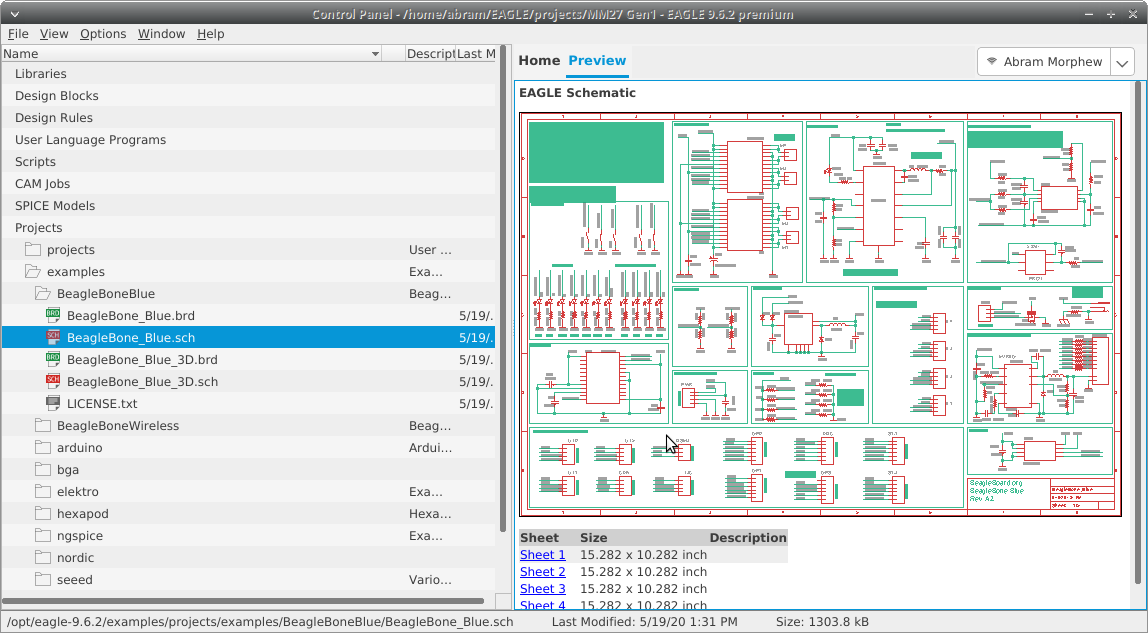
Running Autodesk EAGLE 9.6.2 on Xubuntu 22.04
So, I did a fresh install of Xubuntu 22.04 on a Dell Latitude 7390 with an Intel UHD 620 display adapter. I had some issues with the machine locking up just a few minutes after startup. I was able to resolve this by adding the following kernel option to the /etc/default/grub file.
GRUB_CMDLINE_LINUX_DEFAULT="quiet splash i915.enable_psr=0"
The resolved that issue well enough, and most everything using OpenGL (e.g. Atom, Firefox, etc.) ran just fine after that. The only thing that was giving me trouble now was EAGLE. WebEngineContext would issue an error about not being able to initialize and then the program would seg fault.
WebEngineContext used before QtWebEngine::initialize() or OpenGL context creation failed.
Failed to create OpenGL context for format QSurfaceFormat(version 2.0, options QFlags<QSurfaceFormat::FormatOption>(), depthBufferSize 24, redBufferSize -1, greenBufferSize -1, blueBufferSize -1, alphaBufferSize -1, stencilBufferSize 8, samples 0, swapBehavior QSurfaceFormat::SwapBehavior(DefaultSwapBehavior), swapInterval 1, profile  QSurfaceFormat::OpenGLContextProfile(NoProfile))
[5376:5376:0100/000000.883007:ERROR:broker_posix.cc(41)] Invalid node channel message
Aborted (core dumped)
After much googling, I came across a seemingly unrelated thread where they were removing some of the files from the internal lib folder to force EAGLE to use the system defaults. Since these seemed to be relevant to the error message I was getting, I decided to move the following library files into a folder named “backup” to see what would happen. Those files are shown here.
libX11-xcb.so.1
libxcb-dri2.so.0
libxcb-dri3.so.0
libxcb-glx.so.0
libxcb-present.so.0
libxcb-sync.so.1
libxcb-xfixes.so.0
After that, EAGLE actually opened. Of course, the fonts were huge on a very small 13.3″ screen. I had to go into Options -> User Interface to disable the “High DPI Scaling” option in order to get a more reasonable display.
Now, EAGLE seems to run beautifully. Fingers crossed that we can keep running Autodesk products on Linux in the future!

-
Arduino: Audio Frequency Generator
Back in good ol’ 2012 (the year the world was supposed to end), I posted some code for a simple Arduino controlled low-frequency oscillator (LFO). It has made its way into some very interesting projects over the years, but recently I was asked in the comments if the code could be modified to have a wider frequency output up into the kHz range. I thought it was a good question, so I made the effort to see what the limitations could be.
How It Works
So, the original LFO employs timers on an ATMega328 (or ATTiny85 depending on which version of the code) to generate the audio output. By using a wave table of a basic sine wave stored in an array, one timer (TIMER0) winds up setting the sample rate by grabbing each sample from the array at a configured interval, and the other timer (TIMER2) creates a PWM output on the selected pin (pin 3 in the code). So by setting an 8-bit value on OCR0A, the sample rate can be adjusted which adjusts the frequency on the output of TIMER2. The datasheet for the ATMega328 gives the following formula for the frequency of the output compare register.
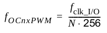
If we take this formula and divide it by the number of samples, we get the output frequency. That means that the output frequency can also be scaled by reducing the number of samples available. So, I made a big output table in LibreOffice and saw that an OCR0A value of 128 was twice the frequency from 255. At 255, I could reduce the number of output samples by half and sweep over the same sample rates but get an increase in output frequency. This introduced a method of frequency scaling. The trade-off, however, is that the sine wave on the output is much less sinusoidal being that it has lower resolution, and that introduces higher order harmonics thus changing the timbre of the sine wave.
Another thing to keep in mind is that the sample rate from the output PWM gets very low and even into the audio range itself. This means that some kind of audio filter is needed on the output. I put a first order low-pass filter using a 2.2k series resistor and a 10 uF capacitor to ground. This worked surprisingly well, though some of the sampling noise shows up on the output at very low frequencies. Being an 8-bit audio signal, this isn’t much to worry about in the grand scheme of things since. I also found that the noise on the output could be lowered by implementing a simple moving average filter in the code on the 10-bit ADC input of the rate control if using a potentiometer to set the frequency. With the timer prescalar set to 64, we should get 64 clock ticks before the next sample is grabbed, so this left some room for some calculations to happen in between sample changes.
It’s all pretty experimental, but it seems to work alright. The frequency range is from around 1 Hz up to 14 kHz (more or less). If you’re using a pot to control the rate, use a linear one as the frequency output gets very logarithmic towards the top of the range.
The Code
// Project: Arduino Audio Frequency Signal Generator // Version: 1.0 // Author: Abram Morphew // Date: 2021.10.12 #define cbi(sfr, bit) (_SFR_BYTE(sfr) &= ~_BV(bit)) #define sbi(sfr, bit) (_SFR_BYTE(sfr) |= _BV(bit)) uint8_t sineTable256[] = { 128,131,134,137,140,143,146,149,152,155,158,162,165,167,170,173, 176,179,182,185,188,190,193,196,198,201,203,206,208,211,213,215, 218,220,222,224,226,228,230,232,234,235,237,238,240,241,243,244, 245,246,248,249,250,250,251,252,253,253,254,254,254,255,255,255, 255,255,255,255,254,254,254,253,253,252,251,250,250,249,248,246, 245,244,243,241,240,238,237,235,234,232,230,228,226,224,222,220, 218,215,213,211,208,206,203,201,198,196,193,190,188,185,182,179, 176,173,170,167,165,162,158,155,152,149,146,143,140,137,134,131, 128,124,121,118,115,112,109,106,103,100,97,93,90,88,85,82, 79,76,73,70,67,65,62,59,57,54,52,49,47,44,42,40, 37,35,33,31,29,27,25,23,21,20,18,17,15,14,12,11, 10,9,7,6,5,5,4,3,2,2,1,1,1,0,0,0, 0,0,0,0,1,1,1,2,2,3,4,5,5,6,7,9, 10,11,12,14,15,17,18,20,21,23,25,27,29,31,33,35, 37,40,42,44,47,49,52,54,57,59,62,65,67,70,73,76, 79,82,85,88,90,93,97,100,103,106,109,112,115,118,121,124 }; uint8_t sineTable128[] = { 128,134,140,146,152,158,165,170,176,182,188,193,198,203,208,213, 218,222,226,230,234,237,240,243,245,248,250,251,253,254,254,255, 255,255,254,254,253,251,250,248,245,243,240,237,234,230,226,222, 218,213,208,203,198,193,188,182,176,170,165,158,152,146,140,134, 128,121,115,109,103,97,90,85,79,73,67,62,57,52,47,42, 37,33,29,25,21,18,15,12,10,7,5,4,2,1,1,0, 0,0,1,1,2,4,5,7,10,12,15,18,21,25,29,33, 37,42,47,52,57,62,67,73,79,85,90,97,103,109,115,121 }; uint8_t sineTable64[] = { 128,140,152,165,176,188,198,208,218,226,234,240,245,250,253,254, 255,254,253,250,245,240,234,226,218,208,198,188,176,165,152,140, 128,115,103,90,79,67,57,47,37,29,21,15,10,5,2,1, 0,1,2,5,10,15,21,29,37,47,57,67,79,90,103,115 }; uint8_t sineTable32[] = { 128,152,176,198,218,234,245,253,255,253,245,234,218,198,176,152, 128,103,79,57,37,21,10,2,0,2,10,21,37,57,79,103, }; uint8_t sineTable16[] = { 128,176,218,245,255,245,218,176,128,79,37,10,0,10,37,79 }; uint8_t sineTable8[] = { 128,218,255,218,128,37,0,37,128 }; uint8_t sineTable4[] = { 128,255,128,0,128 }; uint8_t sineTable2[] = { 255,0 }; uint8_t tWave = 128; uint8_t sWave = 255; uint8_t ruWave = 128; uint8_t rdWave = 128; uint8_t rWave = 128; uint8_t inc = 1; uint8_t r = 0; int n = 32; // number of averages for ADC input (should be a power of 2: 32 max) int ocr[32] = {}; int i = 0; int t = 0; // time delay index for rate sweep int sweep = 1023; // sweep int rate = 0; int waveform; byte d = HIGH; byte down = LOW; // increase freq if LOW, decrease freq if HIGH byte rateSelectPin = 1; byte waveSelectPin = 0; void setup() { pinMode(waveSelectPin, INPUT); pinMode(rateSelectPin, INPUT); pinMode(3, OUTPUT); setupTimer(); OCR0A = 128; } void loop() { // -- Waveform Selection waveform = map(analogRead(waveSelectPin),0,1023,1,7); //waveform = 1; // -- Frequency Selection with ADC pin 1 if (r >= n) r = 0; ocr[r] = map(analogRead(rateSelectPin),0,1023,1015,3); r++; // -- ADC input averaging for(uint8_t c = 0; c < n; c++) { rate += ocr[c]; } rate = floor(rate / n); // Uncomment for frequency sweep /*-------------------- if (t >= 2048) { sweep--; t = 0; } if (sweep <= 4) { sweep = 1023; } t++; rate = sweep; //----------------------- */ // rate scaling with increasing frequency if (rate < 128) { inc = 128; rate = rate * 2; } else if ((128 <= rate) && (rate < 256)) { inc = 64; rate = rate; } else if ((256 <= rate) && (rate < 384)) { inc = 32; rate = rate - 128; } else if ((384 <= rate) && (rate < 512)) { inc = 16; rate = rate - 256; } else if ((512 <= rate) && (rate < 640)) { inc = 8; rate = rate - 384; } else if ((640 <= rate) && (rate < 768)) { inc = 4; rate = rate - 512; } else if ((768 <= rate) && (rate < 896)) { inc = 2; rate = rate - 640; } else if ((896 <= rate) && (rate < 1024)) { inc = 1; rate = rate - 768; } OCR0A = rate; } ISR(TIMER0_COMPA_vect) { if(i >= (256 / inc)) i = 0; switch(waveform) { case 1: OCR2B = sine(i, inc); break; case 2: OCR2B = triangle(i); break; case 3: OCR2B = square(i); break; case 4: OCR2B = rampUp(i); break; case 5: OCR2B = rampDown(i); break; case 6: OCR2B = rand(i); break; case 7: OCR2B = white(i); break; } i++; } void setupTimer() { cli(); /*--- TIMER2 CONFIG ---*/ sbi(TCCR2A,WGM20); sbi(TCCR2A,WGM21); cbi(TCCR2A,WGM22); sbi(TCCR2A,COM2B1); cbi(TCCR2A,COM2B0); sbi(TCCR2B, CS20); cbi(TCCR2B, CS21); cbi(TCCR2B, CS22); /*--- TIMER0 CONFIG ---*/ sbi(TCCR0B,CS00); sbi(TCCR0B,CS01); cbi(TCCR0B,CS02); sbi(TCCR0A, COM0A1); cbi(TCCR0A, COM0A0); cbi(TCCR0A, WGM00); sbi(TCCR0A, WGM01); cbi(TCCR0A, WGM02); cbi(TIFR0,OCF0A); sbi(TIMSK0,OCIE0A); sei(); } int sine(int i, int inc) { if (inc == 1) { return sineTable256[i]; } else if (inc == 2) { return sineTable128[i]; } else if (inc == 4) { return sineTable64[i]; } else if (inc == 8) { return sineTable32[i]; } else if (inc == 16) { return sineTable16[i]; } else if (inc == 32) { return sineTable8[i]; } else if (inc == 64) { return sineTable4[i]; } else if (inc == 128) { return sineTable2[i]; } } int triangle(int i) { if(tWave >= 255) d = LOW; if(tWave <= 0) d = HIGH; if(d == HIGH) tWave = tWave + inc; if(d == LOW) tWave = tWave + inc; return tWave; } int rampUp(int i) { ruWave = ruWave + inc; if(ruWave > 255) ruWave = 0; return ruWave; } int rampDown(int i) { rdWave = rdWave + inc; if(rdWave < 0) rdWave = 255; return rdWave; } int square(int i) { if(i >= (128 / inc)) sWave = 255; if(i < (128/inc)) sWave = 0; return sWave; } int rand(int i) { if(i == (rWave / inc)) rWave = random(255); return rWave; } int white(int i) { return random(255); } -
Arduino: 1-Watt 2m Transmitter with RF Signal Generator
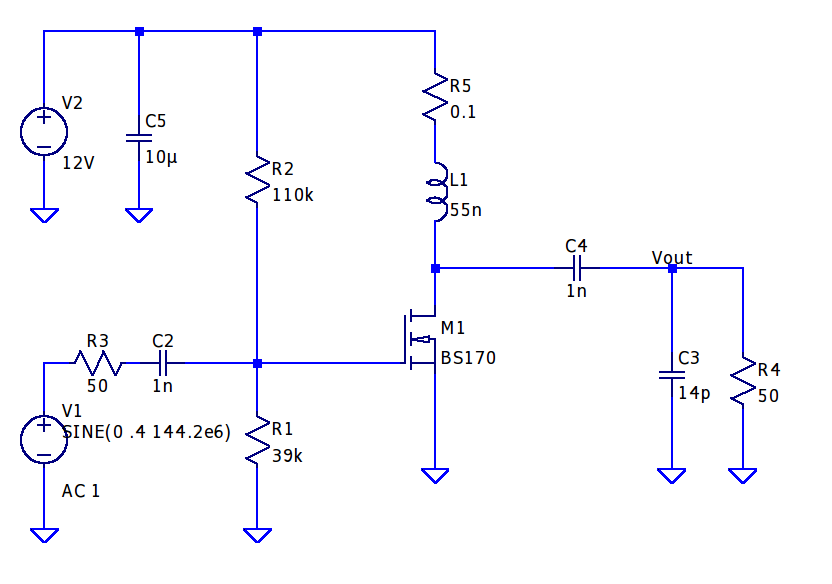
Since I do a lot of RF projects, I wanted to see if I could make a 2m power amplifier using a minimal set of components. I have a number of BS170 MOSFET transistors that I’ve used for dozens of applications over the years from guitar pedal pre-amps to digital control circuits. I started this project by building a class A amplifier on a bare piece of copper laminate. I was able to get 9 dB of gain with a power output of 15 dBm and a quiescent current of 83 mA. The schematic is shown below. R3 and R4 can be omitted if you happen to be building the circuit and replaced with 50 ohm SMA connectors. I used a variable cap at C3 to tune the circuit for maximum output power,
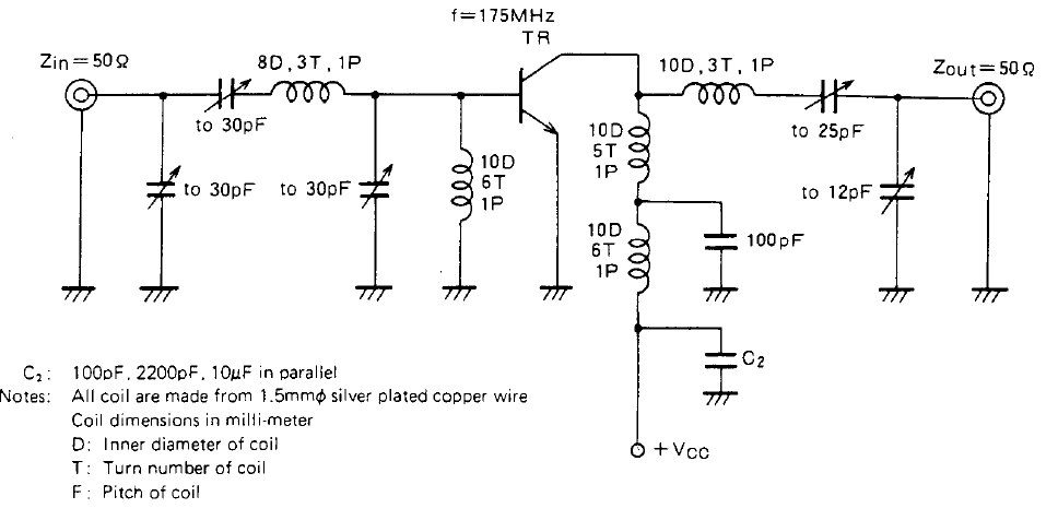
With 15 dBm of output power, I thought this would be adequate to drive a power amplifier stage. I nabbed some 2SC1970 transistors off eBay for a few bucks and started experimenting with the application circuit in the datasheet. This transistor is quite old by modern standards, but they were cheap and in a TO-220 package, so I figured they could take a beating. The standard application circuit was a good jumping off point for starting the design, and I was able to easily make changes to the air-core inductors by compressing and stretching the windings. I wound up just getting as close as I could with the inductors and relying on the variable capacitors in the circuit to get as much power as I could.
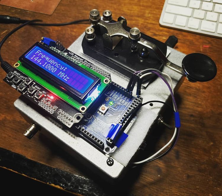
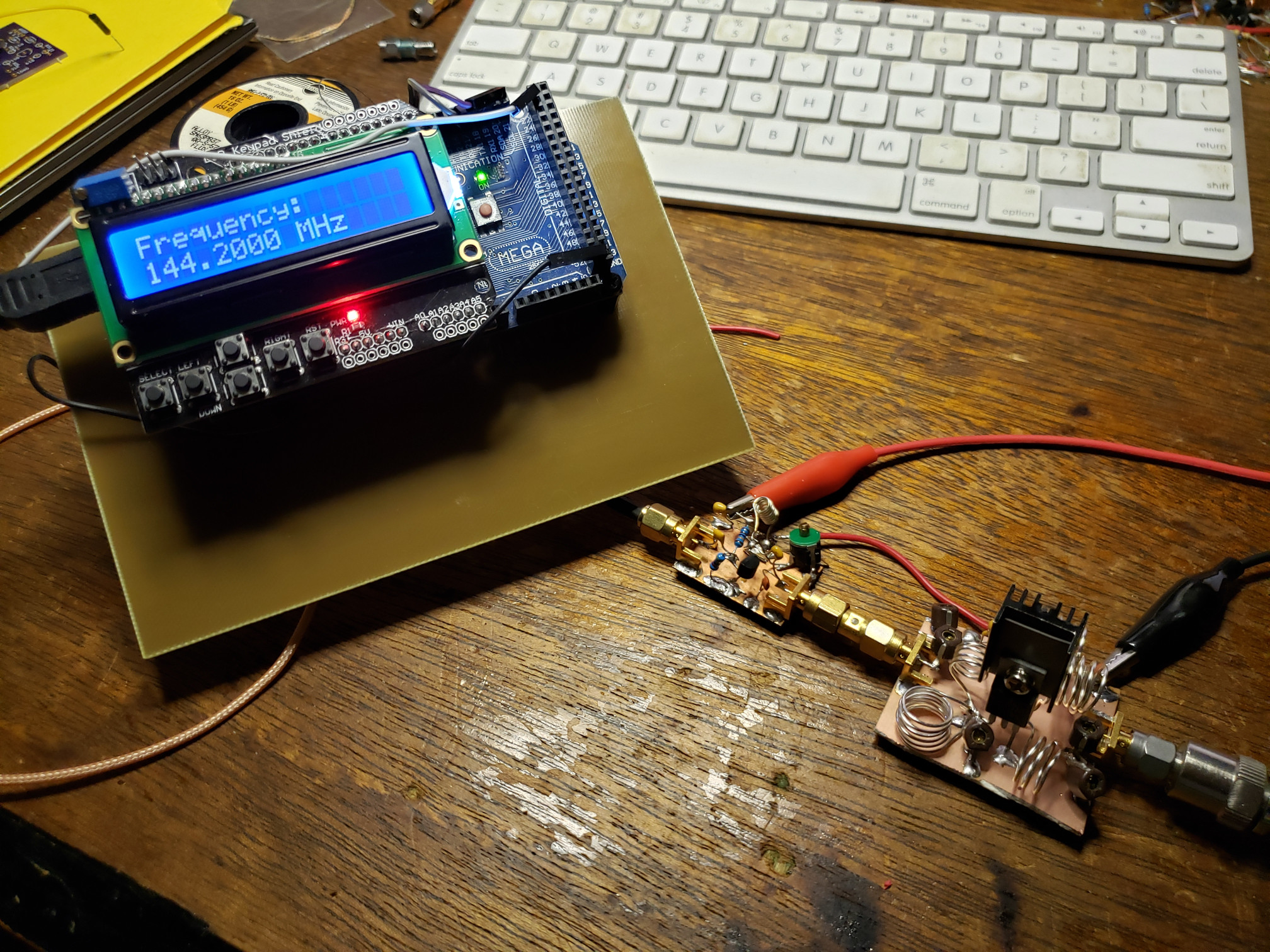
The LO portion of the transmitter was an Si5351 clock signal generator controlled by an ATMega2560 Arduino board. It’s able to get up to 160 MHz (200 MHz now in the Si5351B chips) and is programmed via an I2C port. I setup button 5 (Select) on the LCD shield to enable the LO later on, but I just had it running originally at startup and then connected the straight key in series with the 12V supply (widow-maker style) to the PA.
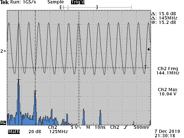
Above is the measured output on the old Tektronix TDS 360 oscilloscope. Measured power output is right at 1 watt. The second harmonic is a little higher than I would have liked, but an added LPF to the output should help fix that right up. The last thing to do was to get out in the rain in January and see if someone could pick it up. I hooked up a 3-element yagi to the output and the signal from the transmitter was picked up by W7YOZ in Shelton, WA some 22 miles to the north east.
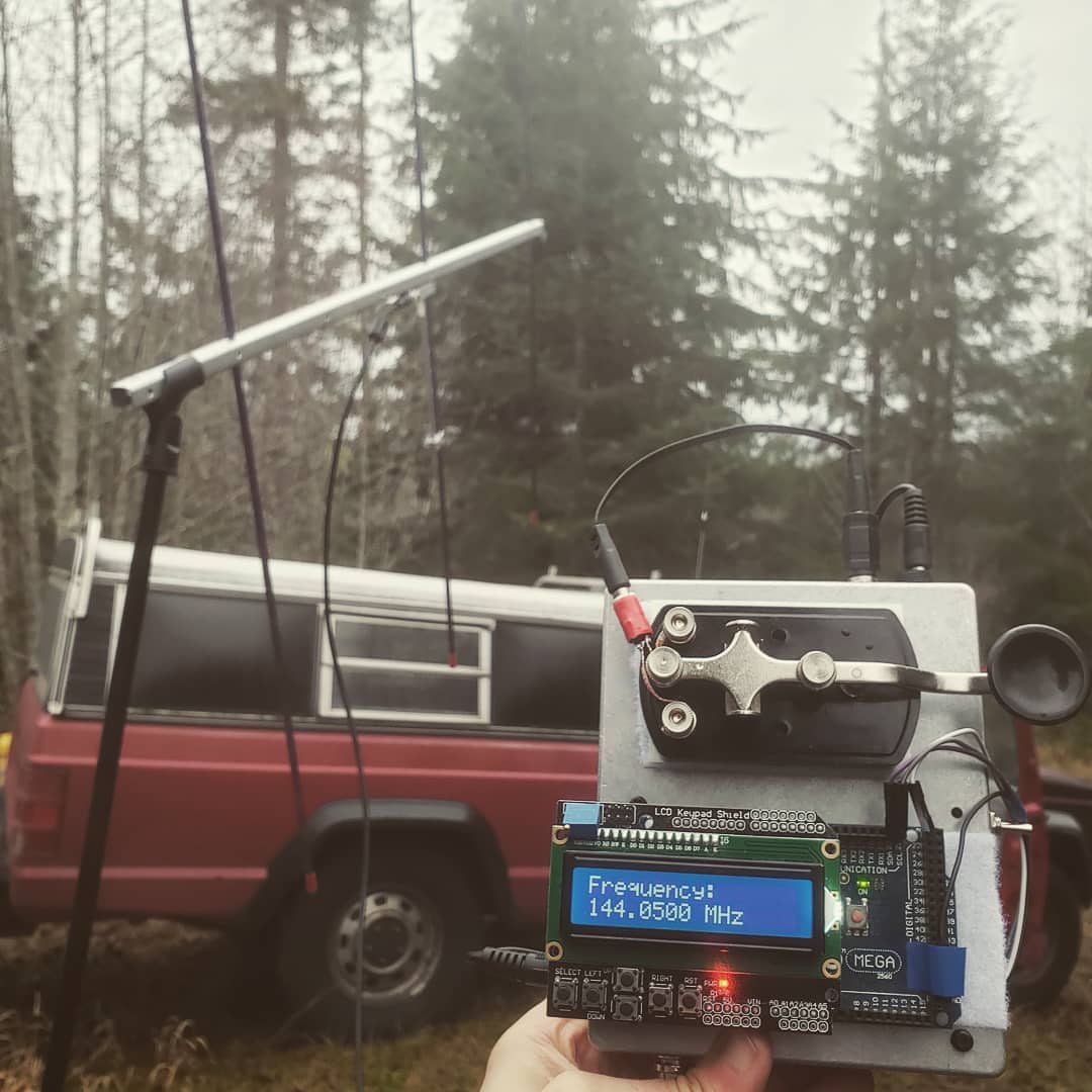
Of course, here is the Arduino code for the RF signal generator using the Adafruit Si5351 clock generator board. The controls need to be incorporated into an interrupt trigger to make the thing more controllable, but it hasn’t been so annoying that I’ve needed to fix it as of yet. Just fair warning in case someone out there in the world decides to use it for anything.
// Arduino RF Signal Generator // author: Abram Morphew // date: 2019.04.25 #include <Wire.h> #include <Adafruit_SI5351.h> #include <LiquidCrystal.h> Adafruit_SI5351 clockgen = Adafruit_SI5351(); LiquidCrystal lcd(8, 9, 4, 5, 6, 7); long frequency = 144100000; long inc = 1000; char* data = "0"; int btn = 0; bool keyPress = false; bool enable = false; void setup() { lcd.begin(16,2); lcd.print("Initialize"); delay(500); /* Initialise the sensor */ if (clockgen.begin() != ERROR_NONE) { lcd.print("Ooops, no Si5351 detected ... Check your wiring or I2C ADDR!"); while(1); } setfrequency(frequency); delay(100); lcd.clear(); } void loop() { if (keyPress == true) { setfrequency(frequency); keyPress = false; } // set title: lcd.setCursor(0,0); lcd.print("Frequency: "); // update frequency lcd.setCursor(0, 1); lcd.print(frequency/1e6,3); lcd.print(" MHz "); btn = readkeypad(); if ((btn == 1) && (frequency + inc <= 155e6)) { frequency = frequency + inc; keyPress = true; delay(100); } if ((btn == 2) && (frequency - inc >= 420e3)) { frequency = frequency - inc; keyPress = true; delay(100); } if ((btn == 3) && (inc < 1e8)) { inc = inc * 10; delay(100); } if ((btn == 4) && (inc > 1e4)) { inc = inc / 10; delay(100); } if (btn == 5) { clockgen.enableOutputs(true); } if (btn != 5) { clockgen.enableOutputs(false); } delay(10); } int readkeypad(){ int adc_key_in = analogRead(0); // int ret = 0; if (adc_key_in < 50) ret = 4; if ( (adc_key_in > 800) && (adc_key_in < 1150)) ret = 0; if ( (adc_key_in > 80) && (adc_key_in < 150) ) ret = 1; if ( (adc_key_in > 250) && (adc_key_in < 350) ) ret = 2; if ( (adc_key_in > 400) && (adc_key_in < 500) ) ret = 3; if ( (adc_key_in > 500) && (adc_key_in < 800) ) ret = 5; //lcd.print(adc_key_in); return ret; } int setfrequency(long frequency) { int m = 0; int n = 0; int fs = 8; clockgen.enableOutputs(false); if (frequency > 55e6) { fs = 8; } else if ((frequency <= 55e6) && (frequency > 25e6)) { fs = 16; } else if ((frequency <= 25e6) && (frequency > 10e6)) { fs = 32; } else if ((frequency <= 10e6) && (frequency > 6e6)) { fs = 64; } else if ((frequency <= 6e6) && (frequency > 3e6)) { fs = 128; } else if ((frequency <= 6e6) && (frequency > 2.1e6)) { fs = 256; } else if ((frequency <= 2.1e6) && (frequency > 1e6)) { fs = 512; } else if (frequency <= 1e6) { fs = 900; } // determine m, n, and d from frequency value m = floor(frequency*fs/25e6); n = ((frequency*fs/25e6) - m)*1000; clockgen.setupPLL(SI5351_PLL_A, m, n, 1000); clockgen.setupMultisynth(0, SI5351_PLL_A, fs, 0, 1); }